cp45头部故障判断.pdf - 第21页
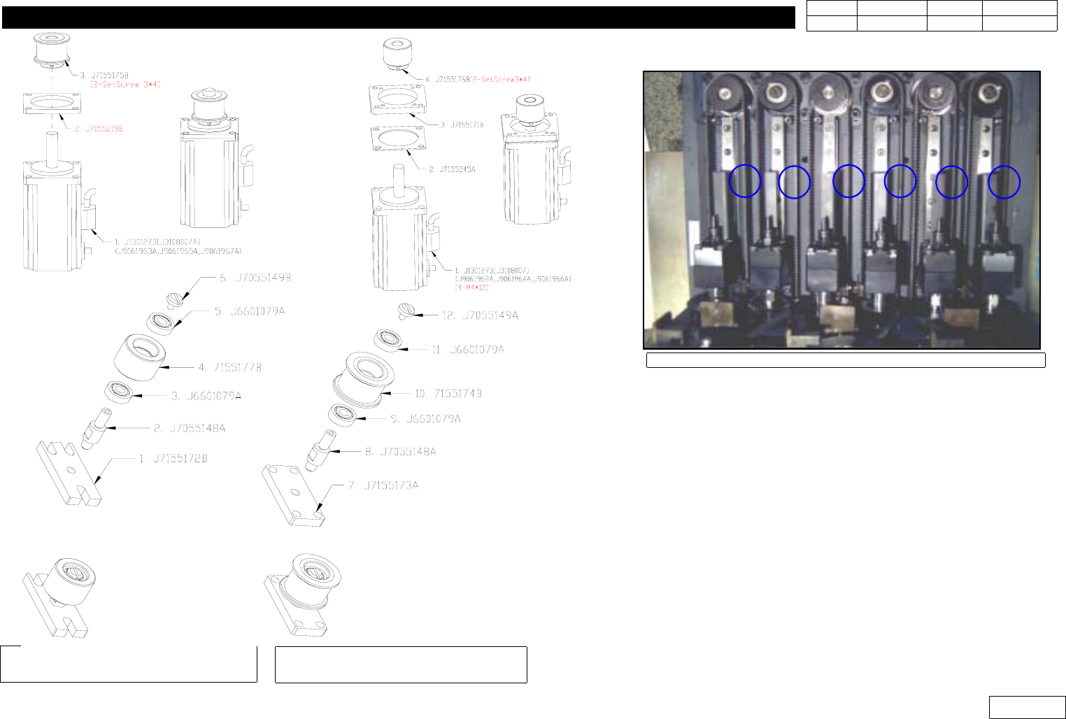
1. Head Module Ver. Date CP45 CP45NEO 00 2004/11 O O 1-1 1-10. Ball Spline Replacement, Check *T o o l s a) Wrench *P a r t: No. Part Co de Description 2 J7055141A SPLINE SHAFT 3 J7055142A SPLINE CAP 13 J9055210A BALL SP…
1. Head Module
Ver. Date CP45
CP45NEO
00 2004/11 O O
1-1
Fig1-9-2 HEAD *2 4 6 Z-Motor and
Z-Pulley sub-assembly
Fig1-9-3 HEAD *1 3 5 Z-Motor and
Z-Pulley Sub Assembly
Fig1-9-4 Position for Z-Axis Belt tension
Note) Part Number is Displayed for CP45NEO Use,
and Motor is Different from CP45F(V)
1. Head Module
Ver. Date CP45
CP45NEO
00 2004/11 O O
1-1
1-10. Ball Spline Replacement, Check
*Tools
a) Wrench
*Part:
No.
Part Code Description
2 J7055141A SPLINE SHAFT
3 J7055142A SPLINE CAP
13
J9055210A BALL SPLINE(CP45NEO)
J9055050A BALL SPLINE(CP45F(V))
55 J1300512 BEARING [6802zz]
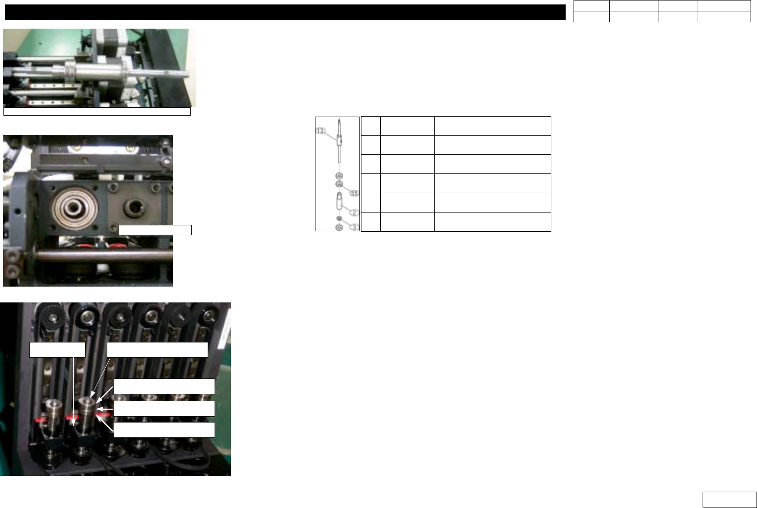
1) Check the Part to be Replaced (Ref. Fig.1-10-1)
- The Nut of Ball Spline and Spline Shaft are Shipped from Factory as Closed Fit
- Bearing 3EA are needed
2) Remove Z-axis Spring to be Replaced, and Separate Joint(CAP),V-Ring and Wavy-washer
3) Separate Spring Cab and Spline Spring
4) Separate Joint Fastening the End Part of Ball Spline
5) Separate Nozzle Holder
6) Separate Ball Spline Ass'y, and Assemble New Ball Spline(Bearing 3EA, Spine Cap 1EA)
(Ref.Fig.1-10-2)
7) Assemble Ball Bearing 2EA at the Upper Part of Ball Spline. At this Time,SpaceisInsertedbtw.
Bearing (Ref. Fig. 1-10-3)
8) Insert the Upper Part of Ball Spline at Slide Arm
Spring Cab
Take care of the assembly direction
Fig.1-10-1 Ball Spline ass'y
Fig.1-10-2 Assemble Ball Spline ass'y
Bearing(696ZZ)
Space(J6601079A)
Bearing(696ZZ)
Slide Arm End of Ball Spline
Fig.1-10-3 Assemble Ball Spline ass'y
1. Head Module
Ver. Date CP45
CP45NEO
00 2004/11 O O
1-1
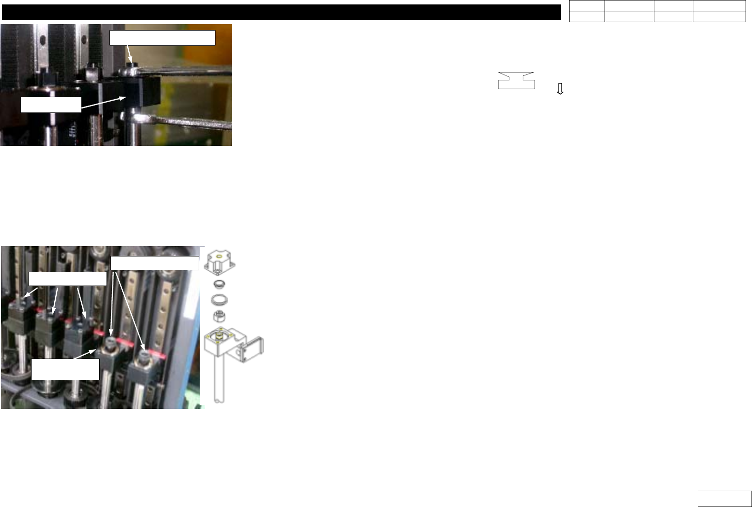
9) Assemble Joint at the Upper Part of Ball Spline (Ref. Fig. 1-10-4)
10) After Assmbling Wavy-washer, V-Ring, Joint(J7155167D), Assemble Z-axis Spring (Ref. Fig. 1-10-5)
( V-Ring Specification; V-6A,Assemble Direction;
)
11) Assemble Nozzle Holder
12) Assemble Spring Cab and Spline Spring
=> Check Vacuum to See if There is Wrong Assemble Part in Diagnosis
* Adjustments after this work
- Head(Fly) Camera Calibration.(Ref. 2-3)
- Head offset Setting.(Ref. 2-16)
- Vision Nozzle Check.(Ref. 1-12)
Fig.1-10-4 Joint set-up
Joint(J7155168A)
Slide Arm
Joint(J7155167D)
Wavy Washer
(J6049000550)
V-Ring(J6304001A)
Fig.1-10-5 V-Ring set-up