cp45头部故障判断.pdf - 第26页
1. Head Module Ver. Date CP45 CP45NEO 00 2004/11 O O 1-1 1-12-2-6) Nozzle( OffsetX, OffsetY, CountX, CountY ) Set Check Range( mm) to Check t he Existence of Nozzle OffsetX, OffsetY are Offset from Vision Center to the C…
1. Head Module
Ver. Date CP45
CP45NEO
00 2004/11 O O
1-1
Displayed on Screen.
In Abnormal Case, Redo the Procedure Above Again
1-12-2) Nozzle Check with Vision
Set as Following Procedure
1-12-2-1) Prerequisite
1) Only Available for the Equipment over MMI Version 2450
2) Nozzle Check of Products after Serial No. 1188 is Available Only with Vision
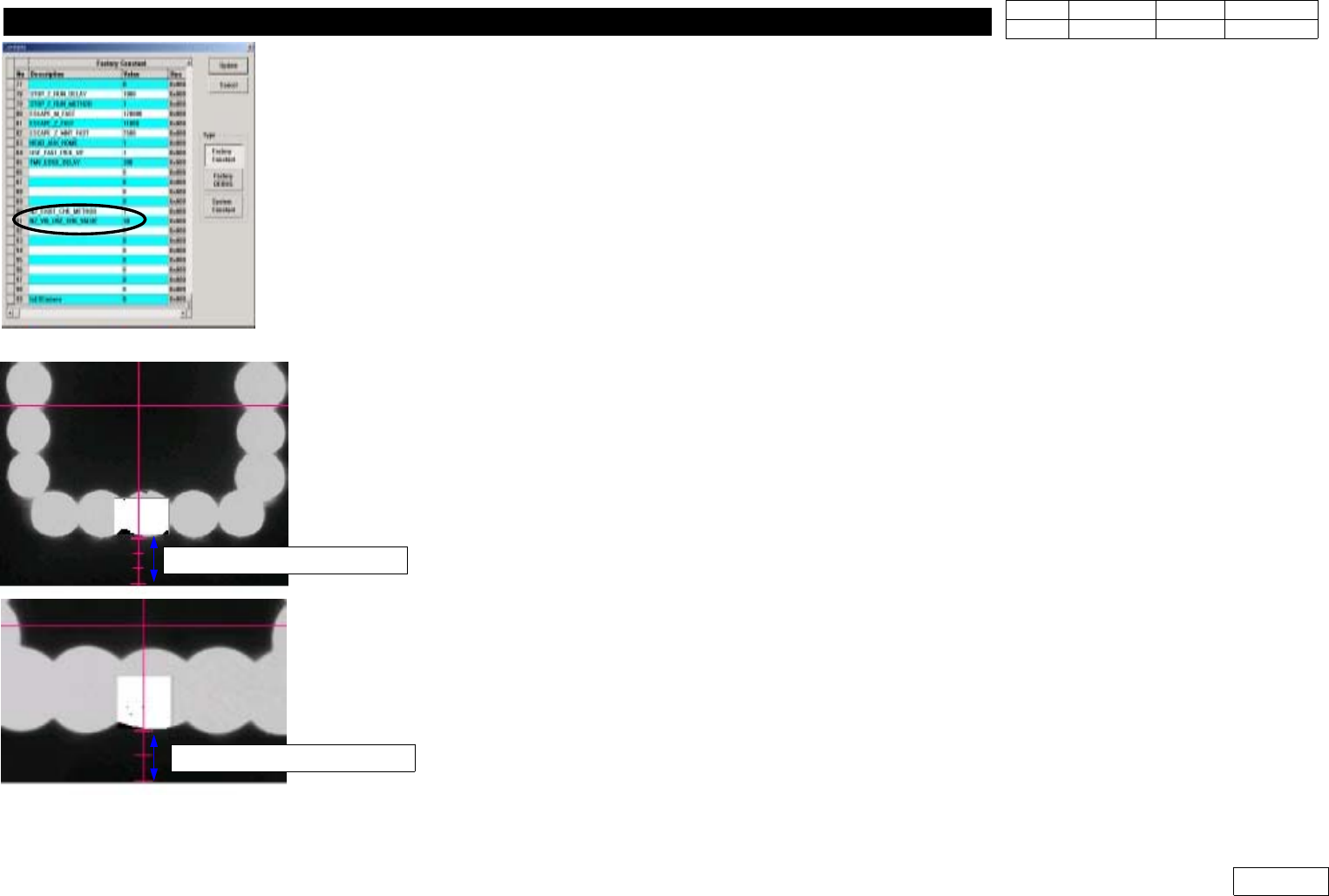
1-12-2-2) Factory Setup Modification (Fig 1-12-2--1)
Set Binary Pixel Count Value => #90, #91 Items
90) NZ_EXIST_CHK_METHOD : Set Vision Use:1, Sensor Use:0
(Only Products before Serial 1188)
91) NZ_VIS_USE_CHK_VALUE : Set 30
1-12-2-3) System Setup
For System Setup, Set Conditions to Sense the Existence of Nozzle with Flying Camera
- Check Pos. Mirror
Set the Angle(deg) of Mirror to Check the Existence of Nozzle
If FOV is 25mm, Make Fourth Graduation under Y-center Axis of Vision and Lower Part of
Outer Light Coincide with Each Other (Ref. Fig 2-12-2-3)
If FOV is 15mm, Make Third Graduation under Y-center Axis of Vision and Outer Light
Coincide with Each Other (Ref. Fig 2-12-2-3)
1-12-2-5) Check Pos. Z
Set the Height of Z-axis(mm) to Sense the Existence of Nozzle
After Removing Nozzle, Make the Position of End Part of Nozzle Holder Coincide with Fourth
Graduation under Y-center Axis of Vision(for FOV 25mm) and the Lower Part of Outer Light
Fig.1-12-2-1 Factory setup
Fig.1-12-2-2 Check pos. Mirror
FOB 25mm =>4 scale
FOB 15mm =>3 scale
1. Head Module
Ver. Date CP45
CP45NEO
00 2004/11 O O
1-1
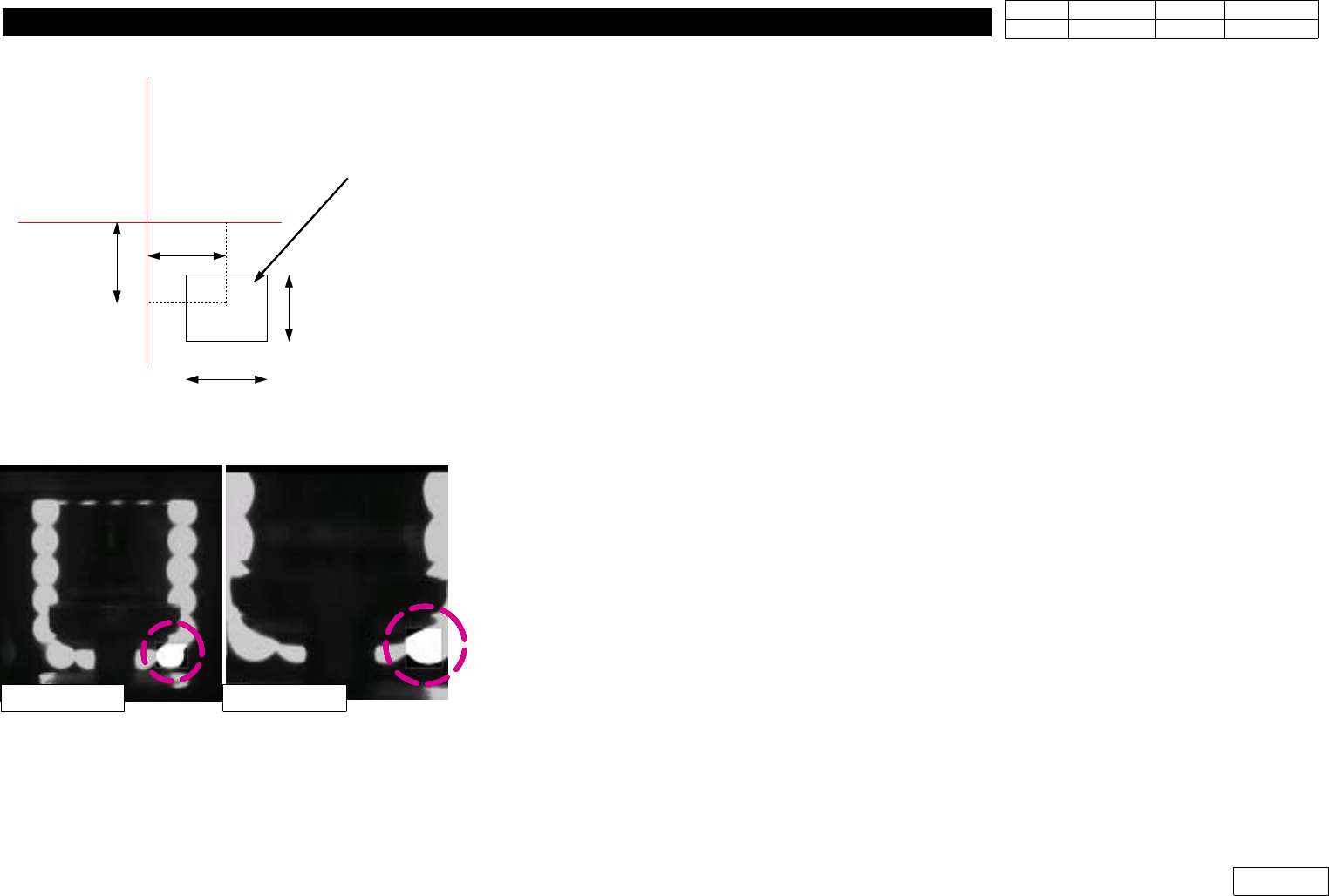
1-12-2-6) Nozzle( OffsetX, OffsetY, CountX, CountY )
Set Check Range(mm) to Check the Existence of Nozzle
OffsetX, OffsetY are Offset from Vision Center to the Center of Check Range
CountX, CountY are Width and Height of Check Range (Fig 1-12-2-4)
1-12-2-7) Light( OffsetX, OffsetY, CountX, CountY )
Set Check Range(mm) to Check the Existence of Light.
Check this Range with the Biggest Nozzle Connected.
The Light is ON if the Value of this Range is over 30%, and OFF if under 30%. (Fig 1-12-2-5)
1-12-2-8) Threshold
The Value is btw. Standard 0 and 255 to Distinguish White Pixel from Black Pixel when Calculating
Binary Pixel Count.
Default is 100.
1-12-2-9) Outer, Inner
SetLightConditiontobeUsedtoChecktheExistenceofNozzleandLight
Set Outer Light for the Mostly Used One and
Default to be Outer:3, Inner:0.
1-12-2-10) Nozzle Exist Value
Standard Value of Binary Pixel Count to Check the Existence of Nozzle and Light
OffsetX
OffsetY
CountX
CountY
Search Area
Vision Monitor
Fig.1-12-2-4
OffsetX, OffsetY, CountX, CountY
Fig.1-12-2-4
Light Check Area
FOB 25mm FOB 15mm
1. Head Module
Ver. Date CP45
CP45NEO
00 2004/11 O O
1-1
1-13. Nozzle Check / Nozzle Holder Check
*Tools
a)Tri-flow, Toothpick
*Part
a) Nozzle Holder Ass'y : J9055046A => for CP45F(V)
b) Common Nozzle Nolder Ass'y:J9055209A => for CP45F(V)NEO
1) Part Code of Nozzle and Property
CP45F(V)
CP45F(V)NEO Diameter(mm)
Name Code Name Code Outer Inner
TN030 J7055180F CN030 J9055133C 0.70 0.28
TN040 J7055246C CN040 J9055134C 0.75 0.38
TN065 J7055267C CN065 J9055136C 1.20 0.65
TN140 J7055131E CN140 J9055159C 2.20 1.40
TN220 J7055132D CN220 J9055139C 3.60 2.20
TN400 J7055133D CN400N J9055218A 6.20 4.00
TN750 J7055135D CN750 J9055142B 9.00 7.50
TN1100 J7055137D CN1100 J9055143C 12.70 11.00
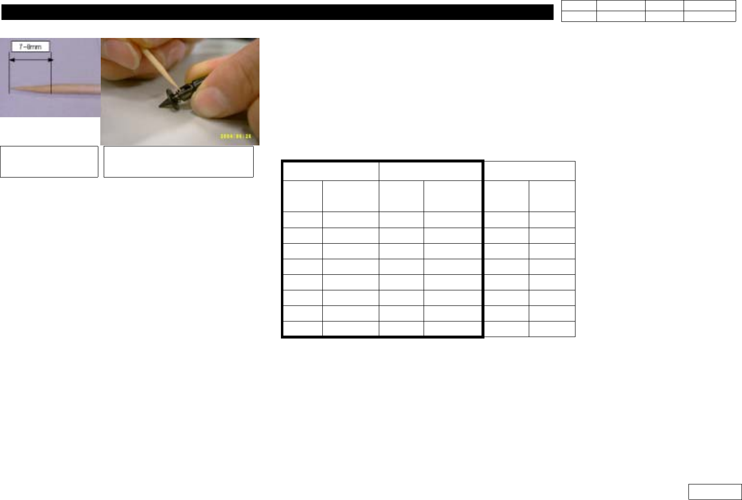
2) Nozzle Cleaning Procedure
2-1) Clean with Remove Spray as Foreign Substance Stuck at Tip Section or Reflection Plate
Causes Sensing Error. Especially, Put the Same Solder for Cleaning if Stain like Solder would
not Come Off by Remove Spray.
2-2) Lubricate and Clean Nozzle Compliance for CP45NEO or Nozzle Holder Compliance for CP45
like Fig. 1-13-1
- Refuel 0.05ml of 'Tri-flow'(The Amount 7-8mm of Toothpick is Dipped) into Pin
Dip toothpick into
Tri-Flow(Lification)
Apply Tri-Flow(Lification) to
Nozzle or Nozzle holder
Fig.1-13-14
Nozzle/Nozzle holder Lubrication