cp45头部故障判断.pdf - 第32页
1. Head Module Ver. Date CP45 CP45NEO 00 2004/11 O O 1-1 1-16. Head Offset Settin g *T o o l s a) Calibration Tool (Tool of ANC Pocket #1) 1) Prerequisite - Calibration of Fix Camera Should be Completed - There Sh ould n…
1. Head Module
Ver. Date CP45
CP45NEO
00 2004/11 O O
1-1
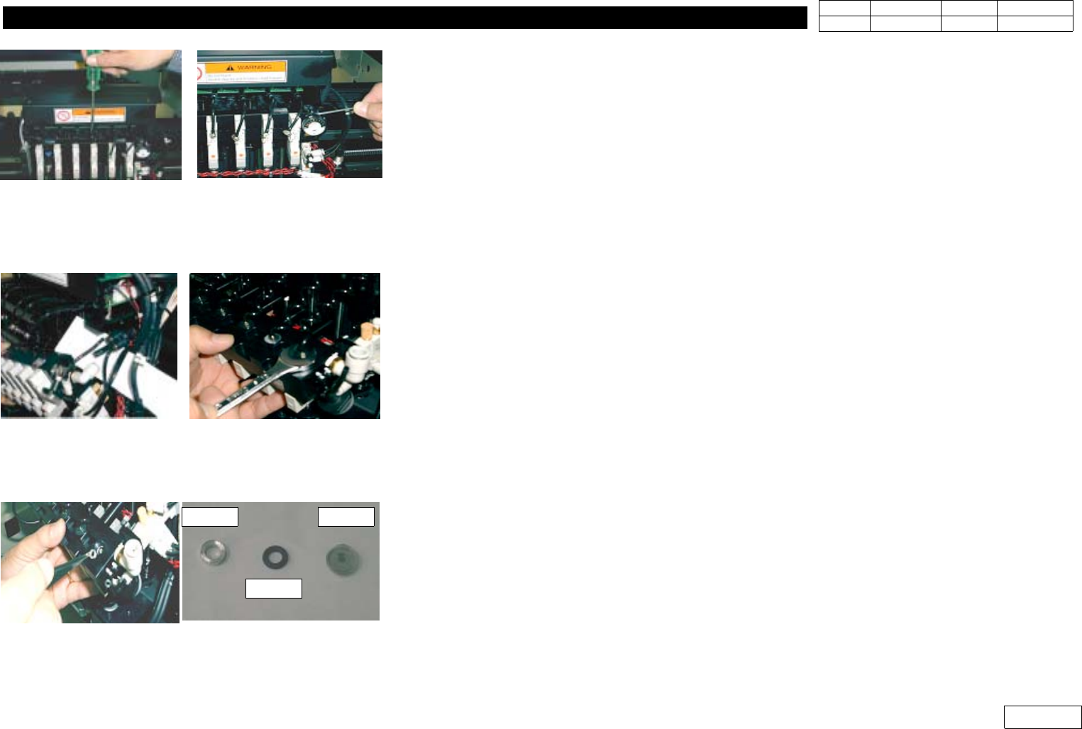
4) Air Disrtibutor Module Internal Filter Replacement Procedure
4-1) Prepare Tools:Flat-tip Screwdriver, 2.5mm Wrench, 12mm Spanner, Tweezer
4-2) Loosen the Plug of Upper Module with Flat-tip Screwdriver(Fig 1-15-3)
4-3) Loosen Bolt 4EA of the Both Sides of Module with 2.5mm Wrench(Fig 1-15-3)
4-4) Separate the Hose of 2 Fitting Part to Ease the Work(Fig 1-15-4)
4-5) Carefully Loosen Filter Ass'y with 12mm Spanner(Fig 1-15-4)
4-6) Loosen Filter Ass'y and Separate Lock Nut, Oil Ring, Filter with Tweezer(Fig 1-15-5) from
Module for Maintenance like Cleaning or Replacement
4-7) When Assembling, Proceed in the Opposite Order of Diassembly.(10 Minutes Required)
When Assembling, Make the Bulging Part of Filter Look Down and Insert it with Tweezer
4-8) Specification of Filter Element
-. Material : SUS304
-. Filtration : 43 micron
-. Pitch : 0.05mm(Mesh:508)
Fig.1-15-3 Disassemble air distributor module
Fig.1-15-4 Disassemble hose, Filter ass'y
Fig.1-15-5 Disassemble Lock-Nut, Oil-Ring,Filter
Lock Nut
Oil Ring
Filter
1. Head Module
Ver. Date CP45
CP45NEO
00 2004/11 O O
1-1
1-16. Head Offset Setting
*Tools
a) Calibration Tool (Tool of ANC Pocket #1)
1) Prerequisite
- Calibration of Fix Camera Should be Completed
- There Should not be Nozzle at Head, and There Should be Caliobration Tool at ANC Pocket#1
- Sys Setup => Camera(F9) => No Real Motion of Tool(Right Menu) Should not be Selected
2) Proceed Head Offset of CP45FV or CP45FVNEO in the Following Direction
Select Sys Setup => Camera(F9) => Calibration => Head Offset
Message
Procedure
First, we must put all nozzles from heads
to ANC To put, Click[Next]
Head Advances Home, Z-axis Goes Down
=> Check if All the Nozzle are Removed
Get tool from ANC to head1
To get it, Click[Next]
Head1 Goes Down so that Tool is Put to Head1
=> Put Calibration Tool in Head1 Manually
Move to center position of [Fix1] camera
To move, Click[Next]
Moving now,
Please wait for a monent.
Head1 Moves to Fix Camera
Calibration ie prepared
To calibrate, click [Next]
Proceed Calibration
=> After Completion, Offset(X,Y) of Head1 is
Printed
Put tool from head1 to ANC
To put it, click[Next]
Head Returns Home, Head1 Goes Down
=> Pick Calibration Nozzle Manually
Get tool from ANC to Head2
To get it, click[Next]
Head2 Goes Down
=> Put Calibration Tool Maunally
...
Proceed Calibration from Head2 to Head6
Head offset calibrastion is finished
Calibration is Completed and Previous/Present
Values of Head Offset are Printed
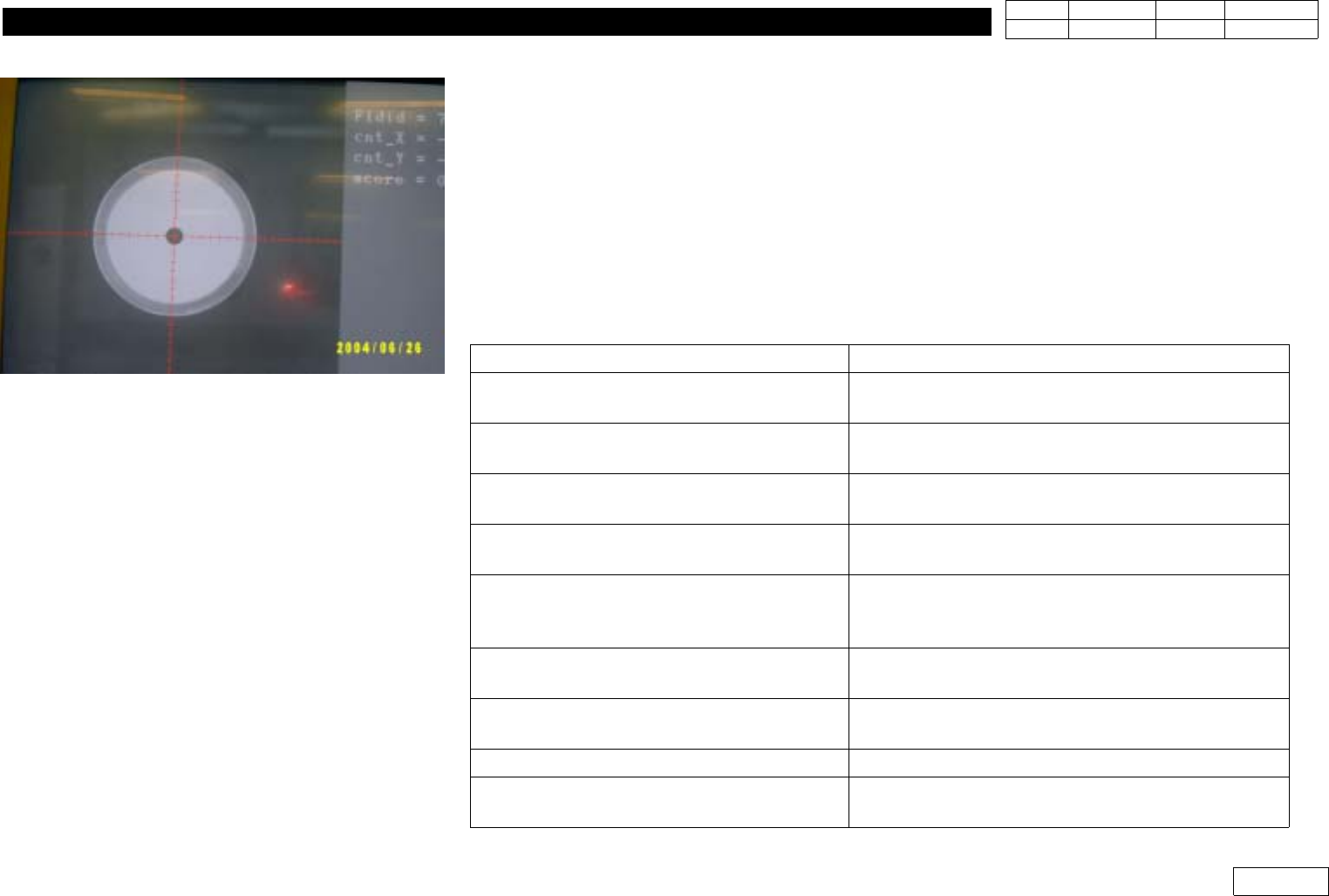
Fig.1-16-1 Head offset calibration
1. Head Module
Ver. Date CP45
CP45NEO
00 2004/11 O O
1-1
- After Checking Printed Old and New Data, Press Update Button to Update
- Head Offset Specification is as Follows:
Item
Specification Remark
X
30* (Head N) (+,-)0.079mm
Head N = 1,2,3,4,5,6
Y (+,-) 0.079mm
If Head Offset Exceed Standard, Assembled Condition of Head Should be Re-checked
3) Head Offset of CP45F or CP45FNEO Setting Procedure
3-1) If Fixed Camera is Available, Install this and Proceed 2) above
3-2) If Upward Vision of CP40 is Available, Install this and Proceed 2) above
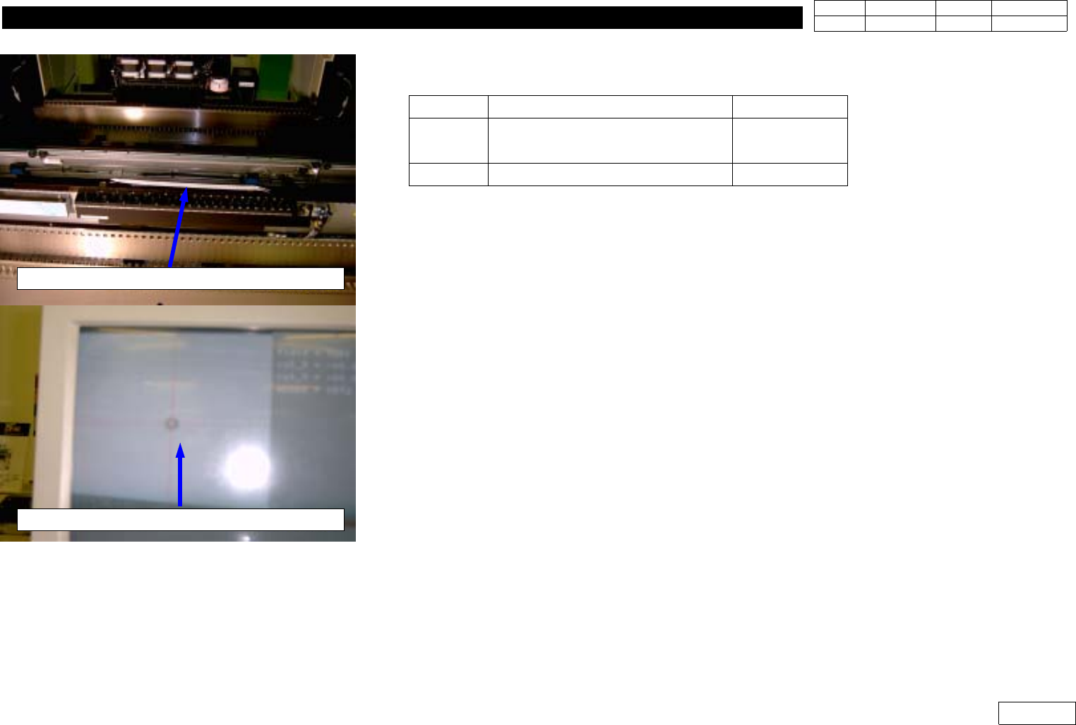
3-3) If Fixed Camera or Upward Vision is not Available(Fig 1-16-2)
- Install Nozzle of the Minimum Diameter(TN040 or CN040) at Head
- Attach Tape at the Center of Upper Conveyor Frame(Teflon Tape is Proper)
- Set the Position of Head1 at the Left End and Move Z-axis Down to Mark the Position
of Head1 on the Tape with Teaching Box
- At the Position, Mark the Positions of Head2~Head6 in the Same Way.
- Using Move Camera, Find the Center of Marked Position of Head1 and Set this
Position for Placement Origin(PBC edit=>Board Definition=>Placement Origin)
- Get the Position of Head1~Head6 at Step Program and Calculate Offset
Note that X-axis Position can be '+' or '-' Depending on Coordinate
If '-' Direction, Convert in '+' to Input(Y-axis is Unnecessary)
Attach tape on the middle of conveyor frame
Teach the center of Mark(Using Move camera)
Fig.1-16-2 Head offset Calibration
(without Fixed camera)