cp45头部故障判断.pdf - 第35页
1. Head Module Ver. Date CP45 CP45NEO 00 2004/11 O O 1-1 2) Move Camer a Offse t of CP45F or CP4 5FNEO Setti ng Procedure 2-1) If Fixed Camera is Available, Install this and Proceed 1) above 2-2) If Upward Vision of CP40…

1. Head Module
Ver. Date CP45
CP45NEO
00 2004/11 O O
1-1
1-17. Move Camera Offset Setting
*Tools
a) Move Camera Calibration Tool
1) Proceed Move Camera Offset of CP45FV or CP45FVNEO as Follows.
Select Sys. Setup => Camera(F9) => Move Cam. Offset
Message
Procedure
Put a tool sheet on Upward(Fix) Camera1 and adjust tool
center
If finish, Click[Next]
Cover Calibration Plate on Upper Surface
of Fixed Camera and Make Camera
Center Coincide with Fixture Center.
Make Fix Camera Center Coincide with
Fixture Center with Target Camera
Move to center position of [Fix1] camera
To move, Click[Next]
Move Move Camera to Fixed Camera with
Teaching Box
Moving now
Please wait for a moment
1. First select move camera and adjust light
2. After then, select Fix camera and adjust light level
3. To calibrate, Click[Next]
Set Target Camera for Fixed Camera and
Move Camera Alternately to Check the
Hole of Screen is Distinguished
Black/White. Adjust Light if Necessary.
Calibration now
Please wait a moment
Result Window is Displayed after
Calibration. Apply the Result.
1. Head Module
Ver. Date CP45
CP45NEO
00 2004/11 O O
1-1
2) Move Camera Offset of CP45F or CP45FNEO Setting Procedure
2-1) If Fixed Camera is Available, Install this and Proceed 1) above
2-2) If Upward Vision of CP40 is Available, Install this and Proceed 1) above
2-3)IfFixedCameraorUpwardVisionisnotAvailable
=> Input the Calculated Value in Sys.Setup => Offset(F4) =>Other Device (Camera *1)
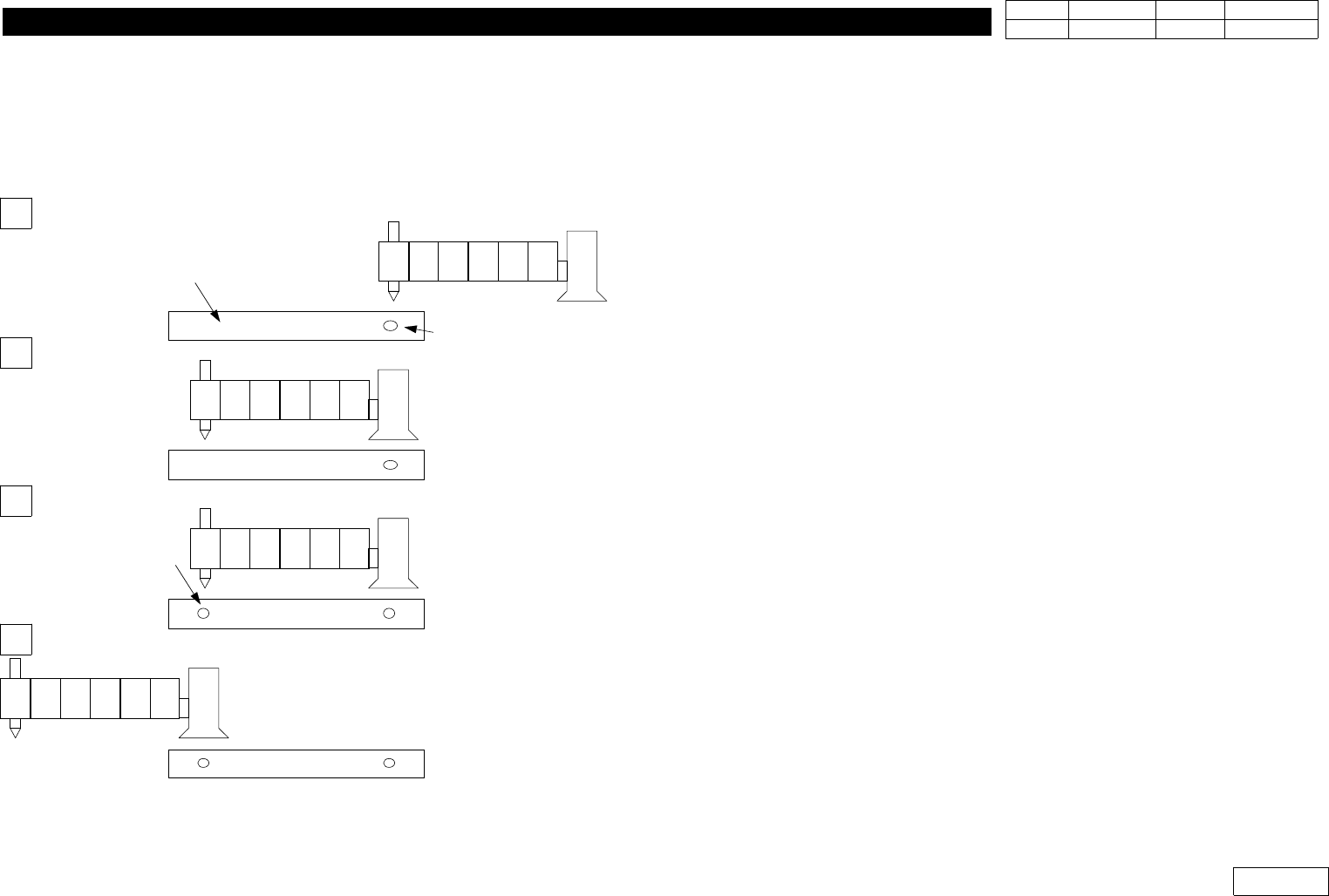
2-3-1) -Install the Nozzle of the Minimum Diameter(TN040 or CN040)
at Head 1
-Attach Tape at the Center of Upper Conveyor Frame
(300mm,Teflon Tape is Proper)
-SetthePositionofHead1ontheTapeCenterandMove
Z-axis Down to Mark the Position of Head1 on the Tape
with Teaching Box
2-3-2) -Read the Center of Marked Position by Move Camera
-Set this Position for Placement Origin, and Save in Step
Program
2-3-3) -Mark the Position of Head1 Once Again w/o Moving Position
2-3-3-1) - Move Move Camera to Save the Center of the Secondly
Marked Position in Step Program
- The Distance btw. these Two Position Becomes the Offset
of Move Camera
- Note that X-axis Position can be '+' or '-' Depending on
Coordinate. If '-' Direction, Convert in '+' to Input
(Y-axis is Unnecessary)
H1 H2 H3 H4 H5 H6
H1 H2 H3 H4 H5 H6
H1 H2 H3 H4 H5 H6
H1 H2 H3 H4 H5 H6
Head *1
Move Camera
Tape on the
conveyor Frame
Second Marking Point
: Head 1
First Marking Point
: Head 1
1
2
3
4
1. Head Module
Ver. Date CP45
CP45NEO
00 2004/11 O O
1-1
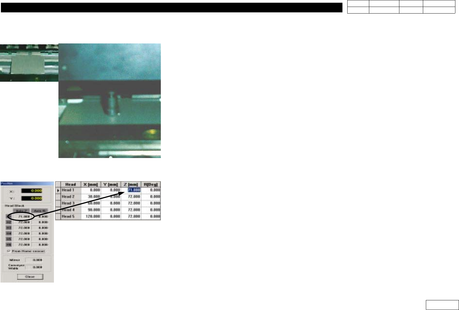
1-18. Z-axis Height Check
*Tools
a) Calibration Plate
*Part
a)
1)
ReturntheNozzleofEachHeadtoANCPocket
- In Case Uninstalling Nozzle from Head Manually, Return it with ANC Menu as Mistake
canbeMadeinMMI
2) Adjust Conveyor to Vision Calibration Plate, Load the Plate to the Install Position
3) With Teach box, Make Z1-axis Contact the Face of the Plate like the Figure
-With Teach Box, Set to Make it Face the Exactly Straight Plate in the Minimum Speed
4) Open View - Current Position in MMI.
5) Select From Home Sensor like the Figure
6) At thie Time, Input the Displayed Value in Offset
7) Proceed from Head1 to Head6 in the same way