HS50电路图 - 第161页
4 Printed Circui t Boards 161 0035344 2-010 101ND 3 90 1 boar d, TSP 200_M convey or cont rol (Sh. 2 of 2) B = Inspectio n label B = Inspectio n label C = revision sta tus 04 02 Stat. 01 03 Modified 14.07.99 04.10.99 15.…
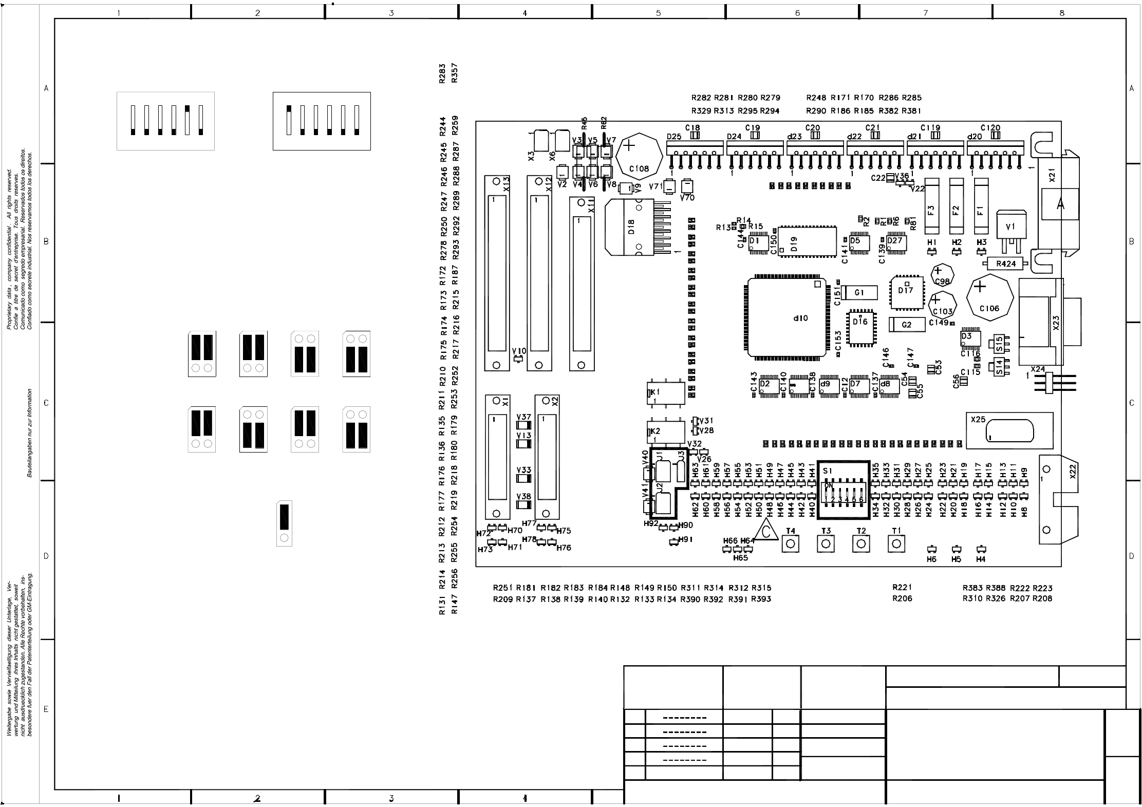
4 Printed Circuit Boards 160
00353442-010101ND3 901 board, TSP200_M conveyor control (Sh. 1 of 2)
04
A = Identification label
C = ESD
Scale 1:1
S1 address coding switch
6312 45
Conveyor 1
ON
132465
ON
S1 address coding switch
Conveyor 2
1111
Error loop
Input conveyor
1
J3
Output conveyor
Siemens
J2
Siemens
J1
1
Siemens
SMEMA
SMEMA
J2 J2
Siemens
1
J1
1
J1
SMEMA
J2
SMEMA
J1
1
Jumper settings
13.07.00 AR
02
01
Stat.
03
Modified
15.05.00
04.10.99
14.07.99
Name
KI
KI
KI
Name Aretz
Date 10.04.00
ATD TD MCH 2
SIEMENS AG
6-layer
PC board
Component layout, component side
Conveyor control
Printed circuit board 901
G32918-L0029-B002-*-0017
00353442-010101ND3
1+
Sheet
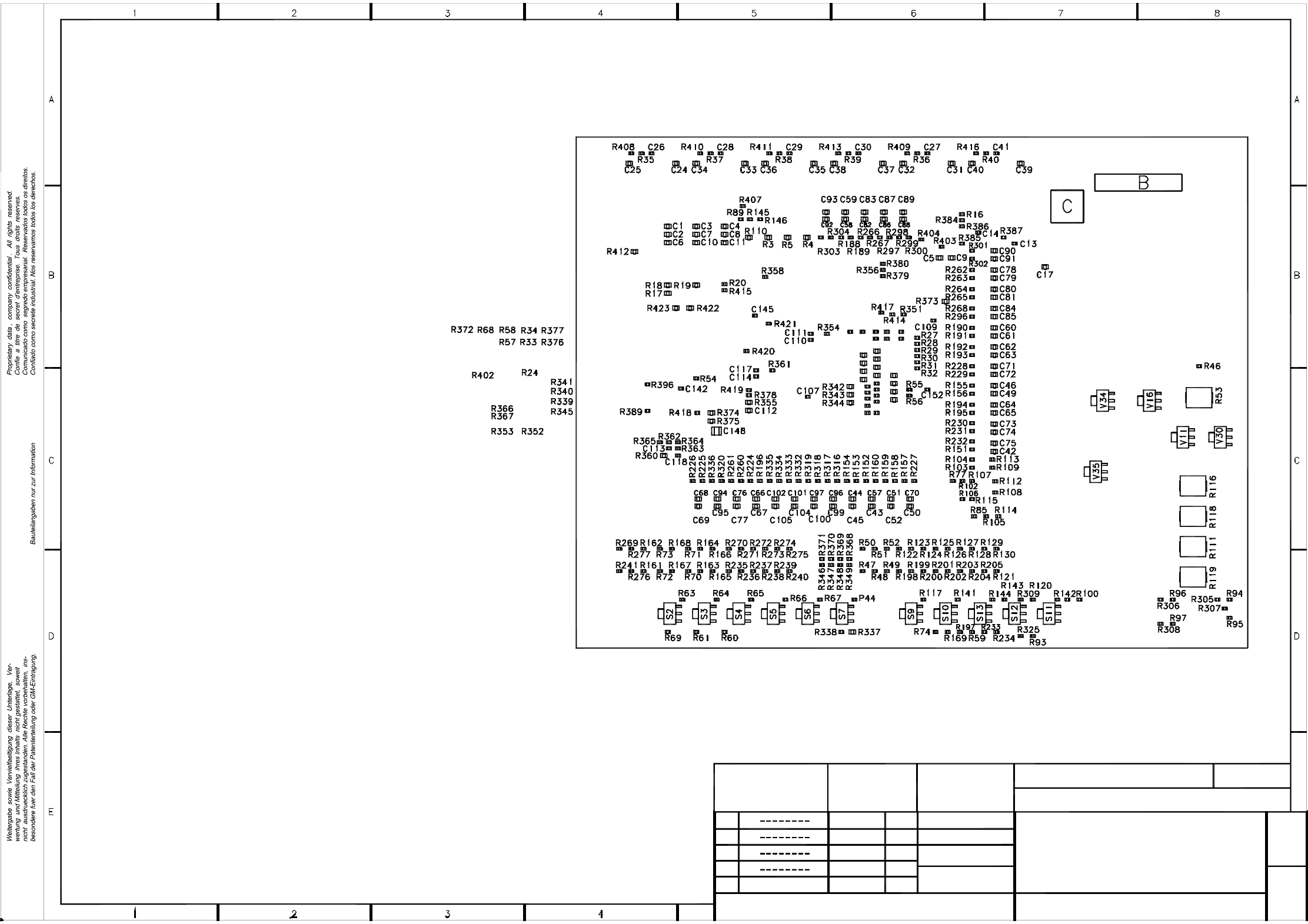
4 Printed Circuit Boards 161
00353442-010101ND3 901 board, TSP200_M conveyor control (Sh. 2 of 2)
B = Inspection labelB = Inspection label
C = revision status
04
02
Stat.
01
03
Modified
14.07.99
04.10.99
15.05.00
13.07.00
AR
Name
KI
KI
KI
PC board
6-layer
Scale 1:1
G32918-L0029-B002-*-0017
Printed circuit board 901
Sheet
2 -
00353442-010101ND3
SIEMENS AG
ATD TD MCH 2
Date 10.04.00
Name Aretz
COMPONENT LAYOUT, SOLDER SIDE
Conveyor control TSP200_M
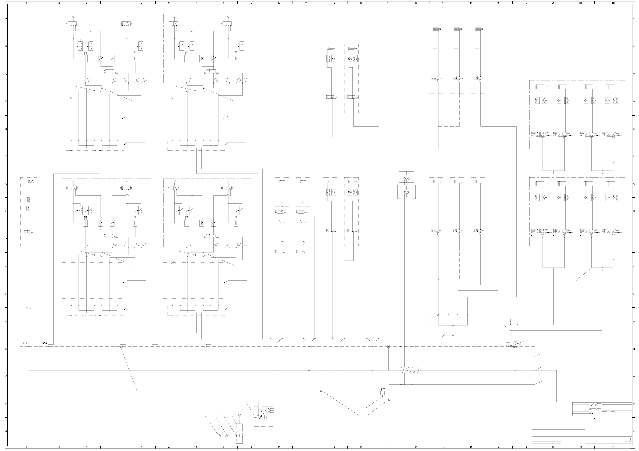
5 Pneumatic Diagrams 162
5 Pneumatic Diagrams
00329906-030101XD0 HS-50 pneumatic system, pneumatic diagram
baba
b
R3
P1
A2
aba
Table
4
Table
3
Table
2
Table
1
PUN-4
PUN-4
PUN-4
PUN-4
A2
R3
P1
A2
R3
P1
R3
P1
A2
p min. = 6.5 bar
(at an air consumption of 950Nl/min.)
B5.1
B5.2 B5.3
B11
B16.4
B16.3
B13.2
B13.1
B12.2
B12.1
B16.1
B16.2
B2
B1
B8
B17
B6B4
B7
Valve block
left 2
00345733-01
00345733-01
00345733-0100345733-01
45 763
Reject circuit
Holding circuit
Placement circuit
Reject circuit
45 763
Reject circuit
Holding circuit
Placement circuit
Reject circuit
Nozzle ø 1mm
Nozzle ø 1,5mm
Nozzle ø 1mm
Nozzle ø 1,5mm
00345185-01
00345185-01
4
576
3
Reject circuit
Holding circuit
Placement circuit
Reject circuit
4
576
3
Reject circuit
Holding circuit
Placement circuit
Reject circuit
Nozzle ø 1mm
Nozzle ø 1,5mm
Nozzle ø 1mm
Nozzle ø 1,5mm
00345185-01
00345185-01
Drag cable
7x hose
4
3
7
6
5
2
1
4
3
7
6
5
2
1
Drag cable
7x hose
Drag cable
7x hose
4
3
7
6
5
2
1
4
3
7
6
5
2
1
Drag cable
7x hose
00329906-030101XD0
S50 pneumatic system
Pneumatic diagram
7.06.99 Stingl
PUN-4
401
B1
Y1
b
S
P
A
a
B
R
401
B1
Y1
b
S
P
A
a
B
R
401
B1
Y1
b
S
P
A
a
B
R
401
B1
Y1
b
S
P
A
a
B
R
PUN-4
PUN-4
PUN-4
401
B1
Y1
b
S
P
A
a
B
R
401
B1
Y1
b
S
P
A
a
B
R
Valve 1
ba
2
3
4
1
5
Valve 2
ba
2
3
4
1
5
Cyl.1
Ø 40 ; Stroke 30
Cyl.2
Ø 40 ; Stroke 30
Valve 1
ba
2
3
4
1
5
Valve 2
ba
2
3
4
1
5
Cyl.1
Ø 40 ; Stroke 30
Cyl.2
Ø 40 ; Stroke 30
Valve 1
ba
2
3
4
1
5
Valve 2
ba
2
3
4
1
5
Cyl.1
Ø 40 ; Stroke 30
Cyl.2
Ø 40 ; Stroke 30
Valve 1
ba
2
3
4
1
5
Valve 2
ba
2
3
4
1
5
Cyl.1
Ø 40 ; Stroke 30
Cyl.2
Ø 40 ; Stroke 30
2
3
4
1
5
FSUAUSESFS
SIEMENS
AUT 5
<6
>6...30
>30...120
>120...400
>400...1000
±0,1
±0,2
±0,3
±0,5
±0,8
Oberfl.:
gehaer tet HRc
einsatzgehaertet
z
R 100
R 25
z
R 6,3
z
R 1
Hierzu gehoert
Koordinatenlis te:
PUN-8
PUN-8
PUN-8
PUN-8
PUN-8
PUN-8
PUN-8
PUN-8
Distributor for
gantry 4
E3
E2
E1
A1
A2
A4
A5
A3
A6
A7
Distributor for
gantry 1
A1
A2
A4
A5
A3
A6
A7
E3
E2
E1
E3
A1
A2
A4
A5
A3
E2
E1
A6
A7
Distributor for
gantry 3
Distributor for
gantry 2
E3
E2
E1
A1
A2
A4
A5
A3
A6
A7
EZH-2,5/9-10
PUN-6
PUN-6
PUN-6
PUN-6
X
PAN-6
PUN-4
PUN-4
PUN-4
PUN-4
PUN-4
PUN-4
PUN-4
PUN-4
(20i)
20,a,b,c,d,e
CO table
Table
4
Table
3
Table
2
right 1
right 3left 4
11
10b
PCB stopper
standard
PCB stopper
(option)
Connection for
bulk case
feeder
(option)
Tape cutter
Substrate
centering
(option)
*) Nozzle closed !
Table
1
Nozzle
changer
(option)
Nozzle
changer
(option)
PCB stopper
standard
PCB stopper
standard
PCB stopper
standard
External
Internal
Nominal value
8 bit
digital
YJ1
b
RP
A
a
p = 5.5 ± 0.5 bar
p = 2.5 ± 0.5 bar
Gantry 2
Gantry 3
Gantry 1
Gantry 4
oder GM-Eintragung vorbehalten.
tung und Mitteilung ihres Inhalts nicht gestattet, soweit nicht
Weitergabe sowie Vervielfaeltigung dieser Unterlage, Verwer-
ausdruecklich zugestanden. Zuwiderhandlungen verpflichten zu
Schadenersatz. Alle Rechte fuer den Fall der Patenterteilung
Copying of this document, and giving it to others and the use
or communication of the contents thereof, are forbidden with-
out express authority. Offenders are liable to the payment of
damages. All rights are reserved in the event of the grant of
a patent or the registration of a utility model or design.
pneumatic adhesive label (mat.-no. 00345740-01) !
In case of modifications please observe information on the
Status N ameDateModified
Stand.
Check.
Author
Date
Name
acc. to ISO 2768 mH
Degree of accuracy
Dimension. variations:
medium
Dimensional variations
Format
Scale
(Material, semifinished products)
(Unmachi ned part no.)
(Model or swage no.)
(Drawing number)
Main no.
Sheet
Sh.
PCB stopper
(option)
left track 2
right track 1
Nozzle
changer
(option)
Nozzle
changer
(option)
10c
12
1
2
4
6,6a,6c
10
14
3,3a
20g
20h
Speed-Placer 6-12Speed-Placer 6-12
Speed-Placer 6-12
Speed-Placer 6-12
00336911-01
PUN-4
PUN-4
PUN-4
PUN-4
5.5 bar
5.5 bar
Y1
b
S
P
A
a
B
R
Y1
b
S
P
A
a
B
R
Y1
b
S
P
A
a
B
R
Y1
b
S
P
A
a
B
R
PUN-4
PUN-4
PUN-4
PUN-4
)(
NN ± N
1
A0
1710xxx Xxxxx xxx xx P
Tiefe:0,3/
2-5 um chemisch vernickelt
FS 03 Ae. 8665 30.06.99 Sti.