HS50电路图 - 第64页
2 Circuit Diagr ams 64 0034983 7-020 101ZD3 Control com plete, HS -50 P CB single conveyo r , TSP200 015 015 AA-BBBB-CCCC 0034983 7-02 SIEME NS PL E A 1 C Draeger 22.12.99 1:2 00349837-020101ZD3 1 010 011 006.. .009 0034…
2 Circuit Diagrams 63
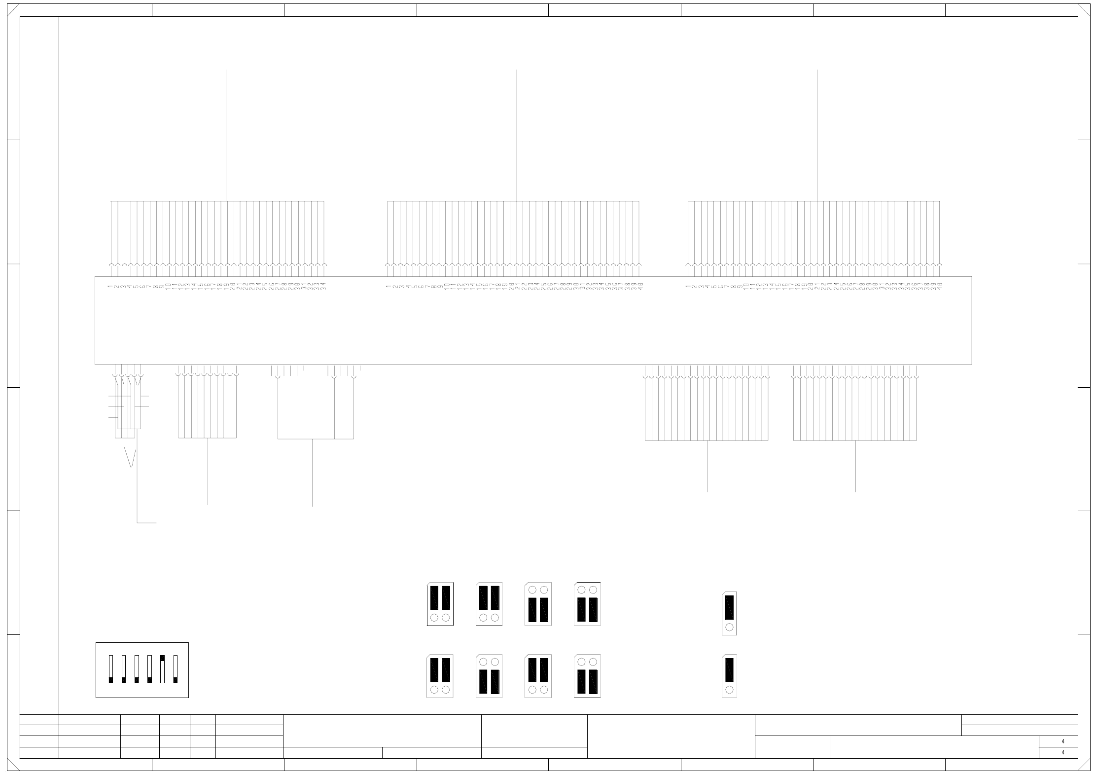
00119046-020101LD3 Single conveyor, stationary side on the right,
wiring, control 1, TSP 200 (Sh. 4 of 4)
SMEMA
J1
SMEMA
1
Jumper settings
(Applies to 00349302 only)
wh
bn
gn
ye
wh bn gn
yeye
wh
bn
gn
=
SIEMENS AG
+
X3ao
3
2
1
4
Lift. table 1
5
6
X6ao
3
2
1
4
Lift. table 2
5
6
M analog
Control:
Lift. table motors
00333592
Key
Key
V_Stoersign.
N_Stoersign.
n.c.
n.c.
n.c.
n.c.
n.c.
2
n.c.
n.c.
n.c.
n.c.
17
20
19
n.c.
n.c.
n.c.
N_GND_24VDC
N_Stoersign.
n.c.
n.c.
n.c.
N_Abgegeben
N_+24VDC
45
n.c.
n.c.
N_SMEMA
234567
N_Anforderung
N_GND_24VDC
31
n.c.
n.c.
n.c.
10
9
n.c.
n.c.
n.c.
n.c.
16
15
14
00335323
125kBits/s
CAN bus
Singel conveyor, stationary side on the right
Conveyor control, conveyor 1 ao
8
1
5
4
7
10
9
8
8
A
B
C
D
E
FF
E
D
C
B
A
8
13
12
11
2
1
6
5
4
7
18
X2ao
X1ao
Interface: preceding
machine
00303036
00303036
Interface: succeeding
machine
V_GND_24VDC
V_+24VDC
V_SMEMA
V_Stoersign.
V_GND_24VDC
6
5
4
7
67
3
2
1
6
3
2
1
4
P5V
P24V
P40V
M digital
M
M
CANL
CANH
CAN-RES
n.c.
V_Erlaubnis
V_Angekommen
n.c.
5 M analog
2
3
1
3
10
9
8
13
12
11
16
15
14
17
20
19
18
X22ao
n.c.
n.c.
Ha
Ha
02
01
01
22.02.00
22.02.00
22.02.00
22.02.00
Haas
#
Wiring, control 1
00119046-020101LD3
X21ao
Adapter cable:
Power supply
00352646
To plug X21ap
CAN-IR
PL EA1 E
Ha
Weitergabe sowie Vervielfaeltigung dieser Unterlage, Ver-
wertung und Mitteilung ihres Inhalts nicht gestattet, soweit
nicht ausdruecklich zugestanden. Alle Rechte vorbehalten, ins-
besondere fuer den Fall der Patenterteilung oder GM-Eintragung. Bauteilangaben nur zur Information
Comunicado como segredo empresarial. Reservados todos os direitos.
Confie a titre de secret d'entreprise. Tous droits reserves.
Proprietary data , company confidential . All rights reserved.
Confiado como secrete industrial. Nos reservamos todos los derechos.
SMD-Placement System Siplace HS50
Product status
Doc. status
Function status
Motor line: PCB conveyor
HS50 Conveyor 1
Conveyor 1, plug X31am
To conversion board
00351931
Sensor line: 1 PCB conveyor
To conversion board
Conveyor 1, plug X32am
00351932
HS50 Conveyor 1
Sensor line: 2 PCB conveyor
HS50 Conveyor 1
00351933
Conveyor 1, plug X33am
To conversion board
X11ao
X12ao
X13ao
Status Modified Date Name
Author
Date
Stand.
Check.
Orig. Repl. f. Replaced by
Sheet
Sh.
Motor + EB
Motor - EB
Motor - BB1
Motor + BB2
Motor - BB2
Motor - ZB
Motor + ZB
Motor - AB
Motor + AB
Motor + BB1
Motor B - BV
Motor A - BV
Motor A + BV
Motor A + BV
Motor A - BV
Motor B + BV
Motor B + BV
Motor B - BV
LS AB (res.)
LS BB2 (res.)
LS ZB (res.)
LS BB1 (res.)
LS EB (res.)
Bero BV
SB BB2
SB BB1
+ 24 V
+ 24 V
GND
GND
SB EB
SB AB
SB ZB
GND
+ 24 V
Code 3 (Opt.)
ESCH BRA
Code 2 (Opt.)
Code 1 (Opt.)
A3 (Opt.)
A2 (Opt.)
A1 (Opt.)
E6 (Opt.)
E5 (Opt.)
E4 (Opt.)
E3 (Opt.)
E2 (Opt.)
E1 (Opt.)
Code 3 (Opt.)
Code 2 (Opt.)
Code 1 (Opt.)
Ventil ST UELP
Bero ST UELP
SB UELP
Ventil ST BB2
Bero ST BB2
Ventil ST BB1
Bero ST BB1
Bero HT 2 u
Bero HT 2 o
Bero HT 1 u
Bero HT 1 o
ESCH BRZ
A3 (Opt.)
A2 (Opt.)
A1 (Opt.)
E6 (Opt.)
E5 (Opt.)
E4 (Opt.)
E3 (Opt.)
E2 (Opt.)
E1 (Opt.)
GND
VCC
Lifting table 2, topHT2o
Lifting table 2, bottomHT2u
SB
UELP
ST
LS
Sonar prox. switch
Stopper
Excess length PCB
Light barrier
Lifting table 1, bottomHT1u
HT1o
BB1
AB
BRA
BV
BRZ
EB
BB2
ESCH
Abbreviations
E
A
Width narrower
Lifting table 1, top
Width adjustment
Input conveyor
Limit switch
Input
Output conveyor
Placement sector 1
Width wider
Placement sector 2
Output
0034826700348267 00348267
00349302 or 00353442
(TSP200 or TSP200_M)
S1 address coding switch
ON
123456
TSP200
1111
Error loop
Error loop
Input conveyor
J4
1
1
J3
Output conveyor
J2
Siemens
Siemens
J1
1
Siemens
SMEMA
SMEMA
J2 J2
Siemens
1
J1
1
J1
J2
2 Circuit Diagrams 64
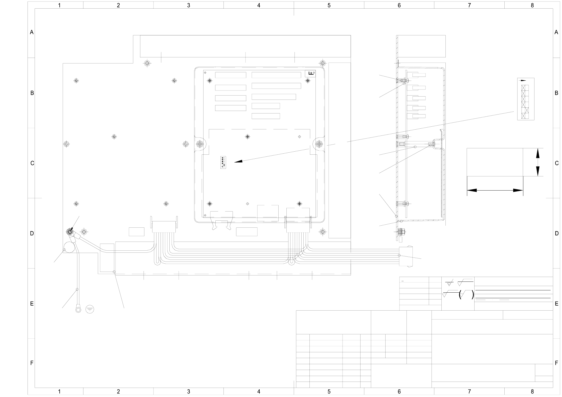
00349837-020101ZD3 Control complete, HS-50 PCB single conveyor, TSP200
015
015
AA-BBBB-CCCC
00349837-02
SIEMENS PL EA 1
C
Draeger22.12.99
1:2
00349837-020101ZD3
1
010
011
006...009
00342987-01
002
005
003
A
D
012
E
013
1
2
3
4
5
6
ON
004
(Unmachined part no.)
(Material, semifinished products)
Format
Scale
NameDate
Author
Check.
Stand.
Degree of accuracy
acc. to ISO 2768 mH
Dimensional variations:
medium
Dimensional variations
Surface:
gehaertet HRc
einsatzgehaertet
Comprises
coordinates list:
Tiefe:0,3/
Ground connection cable
Cable duct 65x46 l=335±5mm "X" means to break off one rib
Adapter cable 00352646-01
Cable duct 65x30 l=250±5mm "X" means to break off one rib
Cable duct 65x30 l=300±5mm "X" means to break off one rib
Label F: AO assembly designation
Label E: grounding
Label D: inspection label
20
40
Conveyor 1
Pos. of
binary switches
Label A
Label C 00349837-FS
XXX XXXXXXXXXXXXXXXXXXXX
XXXXXXXXXXXXXXXX
016
001
Copying of this document, and giving it to others and the use
or communication of the contents thereof, are forbidden with-
out express authority. Offenders are liable to the payment of
damages. All rights are reserved in the event of the grant of
a patent or the registration of a utility model or design.
Weitergabe sowie Vervielfaeltigung dieser Unterlage, Verwer-
tung und Mitteilung ihres Inhalts nicht gestattet, soweit nicht
ausdruecklich zugestanden. Zuwiderhandlungen verpflichten zu
Schadenersatz. Alle Rechte fuer den Fall der Patenterteilung
oder GM-Eintragung vorbehalten.
Draeg
Frank
Draeg
04.05.00
22.12.99
10.07.00AM9443
Status Modified
new
Date Name
Sheet
Sh.
Main no.
(Drawing number)
Control, complete
HS50 PCB single conveyor
(Model or swage no.)
FS 02
1
A3
Tiefe:0,3/
FS 01
US 02
FSUAUSESFS
SIEMENS
PL EA
<6
>6...30
>30...120
>120...400
>400...1000
±0,1
±0,2
±0,3
±0,5
±0,8
gehaertet HRc
einsatzgehaertet
z
R 100
z
R 6,3
z
R 2
2 Circuit Diagrams 65
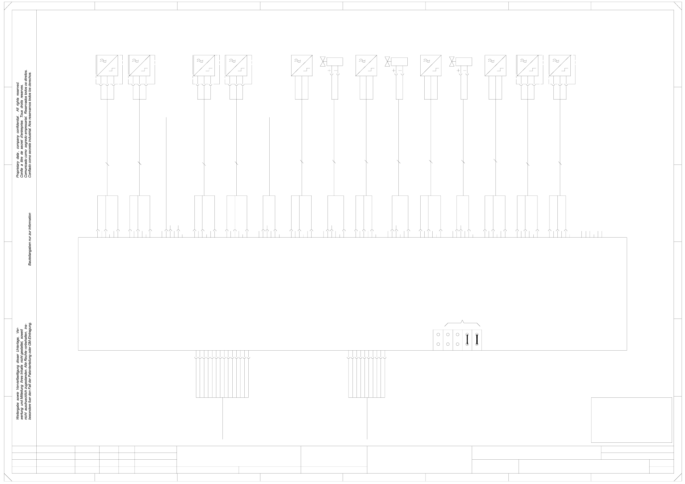
00334490-010201LD3 SLIO module, PCB 1 (am), conveyor 1, TSP 100 (Sh. 1 of 5)
B10_1
(conveyor 1)
A
I
O
0V
SLIO module, PCB 1 (am)
3
2
1
6
5
24V
O
I
0V
24V
24V
O
I
+
-
B8_1 B9_1
A
0V
0V
24V
O
I
0V
0V
24V
0V
0V
24V
0V
Key
Key
X14_1
0V
PORT 13
PORT
wh
bn
bl
bk
bk
bl
bn
(conveyor 1)
bl
bn
bk
bl
bn
(conveyor 1)
(conveyor 1)
00343225
+
-
+
-
A
+
-
X8_1 X9_1
Z1_1 Z2_1 B13_1 B14_1
00336432
0V
0V
bk
bl
bn
A
X6_1 X7_1
00332516
00332517
00343239
+
-
A
+
-
00343239
bk
A
bk
bn
bl
bk
bn
wh
bn
Leh
Leh
Leh
01
02
01
11.02.98
11.02.98
11.02.98
11.02.98
Haas
#
SLIO module, PCB 1 (am) (conveyor 1)
00334490-010201LD3
00332518
00332519
00343239
00343239
bk
bl
bn
PL EA1 E
=
SIEMENS AG
+
14
13
1
6
5
4
7
34
wh
bn
not used
10
9
00318137
3
2
678
1234
1
6
8
Power supply,
SLIO conveyor
00335233
11
D
E
F
8
CAN bus,
125 kbits/s
00335323
A
0V
24V
0V
5
4
7
10
9
CANL
CAN, ground
n.c.
Reset
CAN, ground
CANR
n.c.
12
00318137
X17am
GND
+24V
GND
1
5
12
GND
GND
bn
bk
bl
not used
not used
5
bl
bn
bk
bl
bn
B15_1
Cable: valve - stopper,
5678
A
B
C
bn
gn
24V
F
E
D
C
B
bk
bl
B11_1
00332522
0V
24V
0V
0V
24V
00332512
00336089
(conveyor 1)
A
+
n.c.
n.c.
n.c.
+24V
+24V
+24V
GND
00336091
+5V
+5V
GND
+5V
GND
+
-
Prox. switch: add. stopper
Prox. switch: position
bottom position
bn
00336095
bk
(conveyor 1)
excess length
Cable: valve - add.
stopper, excess length
width adjustment
Cable: bero for
ceram. subst. centering 1
placement section 1
B12_1
CAN bus,
addresses
CAN bus,
end
wh
Keying
00333592 (W1)
Control signals, PCB conveyor,
bl
bn
00336094
3
2
Valve:
stopper,
placement
(conveyor 1)
A
+
-
(conveyor 1)
add.
Z3_1
Valve:
(conveyor 1)
stopper,
excess length
-
A
+
-
(conveyor 1)
ceramic
centering 1
(conveyor 1)
00332520
(conveyor 1)
A
substrate
bn
00336433
Prox. switch:
lifting table 1,
top position
placement section 1
Prox. switch: stopper retracted,
placement section 2
placement section 2
(conveyor 1)
Prox. switch:
lifting table 2,
bottom position
(conveyor 1)
Prox. switch:
lifting table 2,
Cable: bero for
ceram. subst. centering 2
X19am
X20am
X21am
X22am
X23am
Valve:
stopper,
placement
lifting table motors
00333592 (W1)
Control signals, PCB conveyor,
lifting table motors
X18am
(conveyor 1)
section 2
24V
O
I
(conveyor 1)
section 2
Prox. switch:
stopper,
excess length
0V
24V
24V
O
I
0V
0V
add.
Prox. switch:
width
adjustment
(conveyor 1)
position
Prox. switch:
00332524
B6_1 B7_1
substrate
Prox. switch:
(conveyor 1)
ceramic
centering 2
0V
0V
I
0V
24V
bottom position
(conveyor 1)
Prox. switch:
lifting table 1,
top position
24V
O
I
0V
24V
3
2
top position
(conveyor 1)
Prox. switch:
stopper,
placement
(conveyor 1)
section 1
0V
0V
24V
(conveyor 1)
section 1
Prox. switch:
stopper,
placement
O
I
3
2
1
0V
24V
24V
O
I
1
6
5
4
3
2
1
bottom position
Prox. switch: stopper retracted,
Cable: valve - stopper,
5
4
3
0V
24V
24V
O
I
24V
O
5
4
3
24V
O
I
0V
24V
3
2
1
6
5
4
3
1
6
5
4
24V
O
I
1
6
5
O
I
0V
24V
24V
5
4
X15_1
wh
6
5
4
3
2
X10am
wh
bn
X3am
X6am
X12am
X16am
6
5
4
3
2
1
6
2
1
6
2
1
6
5
4
1
6
bk
bl
bn
2
1
6
5
4
Key
X9am bk
bl
bn
X11am bk
2
1
6
5
4
3
2
X14am
X15am
Key
4
3
2
1
6
bl
bn
1
6
5
X8am
wh
bn
2
3
4PORT
PORT 5
PORT
3
2
1
6
5
4
3
PORT
PORT
10
5
4
Key
3
2
Key
Key
00343224
bl
bk
Key
X7am bk
bl
bn
X5am
11
12PORT
24V
O
I
bl
bn
Key
X13am bk
bl
bn
4
3
2
bn
bk
bl
bn
bk
0V
24V
24V
O
I
4
PORT 1
PORT
PORT
0V
24V
24V
Key
Key
Key
Key
PORT
6
7
8PORT
PORT 9
PORT
14
15
16PORT
Key
Key
Key
00332521 (conveyor 1)
00343226
00343227
X1am
X2am
X4am
top position
(conveyor 1)
Function status
Product status
Doc. status
SMD Placement System SIPLACE HS50
Prox. switch: lifting table 2,
Prox. switch: lifting table 2,
Prox. switch: lifting table 1,
Prox. switch: lifting table 1,
not used
not used
not used
PLEASE NOTE!
In case of modification
this document will
not be replaced.
Status DateModified Name Stand. Orig. Replacement for Replaced by
Author
Date
Check.
Sheet
Sh.
3 X 0,14mm²
3 X 0,14mm²
3 X 0,14mm²
3 X 0,14mm²
3 X 0,14mm²
2 x 0,25mm²
3 X 0,14mm²
2 x 0,25mm²
3 X 0,14mm²
2 x 0,25mm²
3 X 0,14mm²
3 X 0,14mm²
3 X 0,14mm²
TSP100