HS50电路图 - 第67页
2 Circuit Diagr ams 67 0033449 0-010 201LD3 S LIO mo dule PC B2 (an) , convey or 2, TS P100 (S h. 3 of 5) n.c. n.c. n.c. n.c. +24V +24V bl +24V GND +5V +5V GND +5V GND GND GND bk bl bn 0V 24V 24V 0V 24V 0V 34 0V Prox. sw…
2 Circuit Diagrams 66
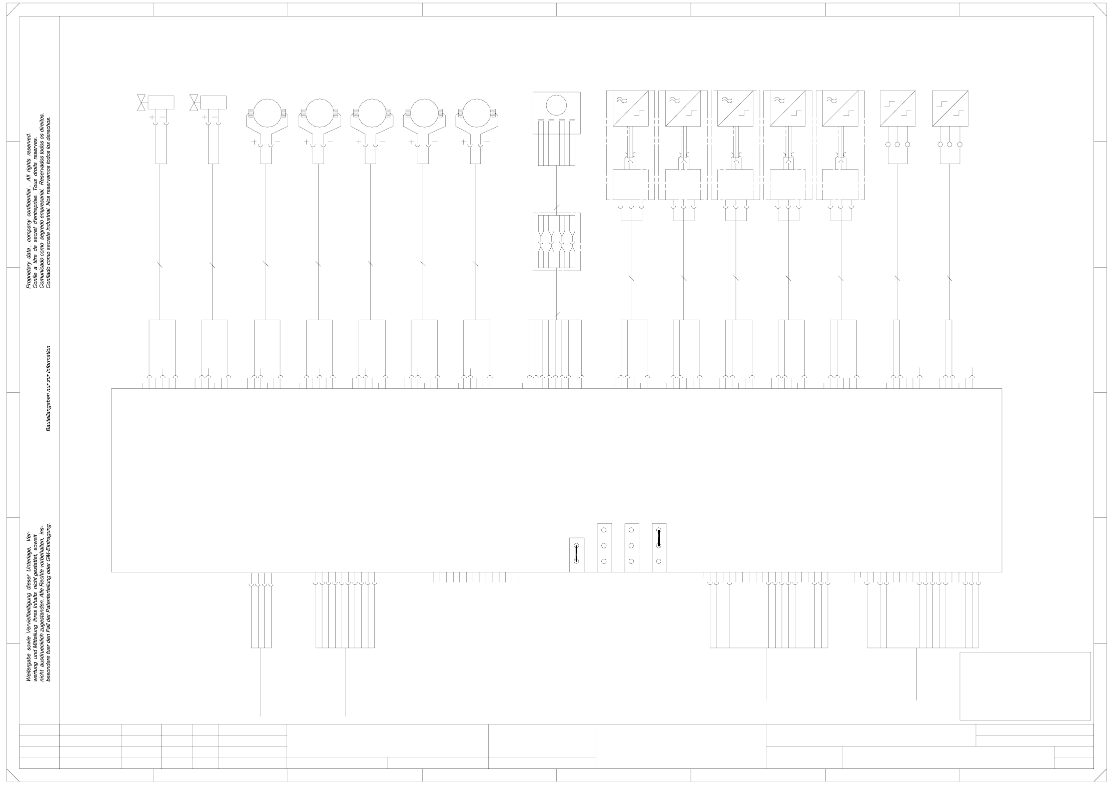
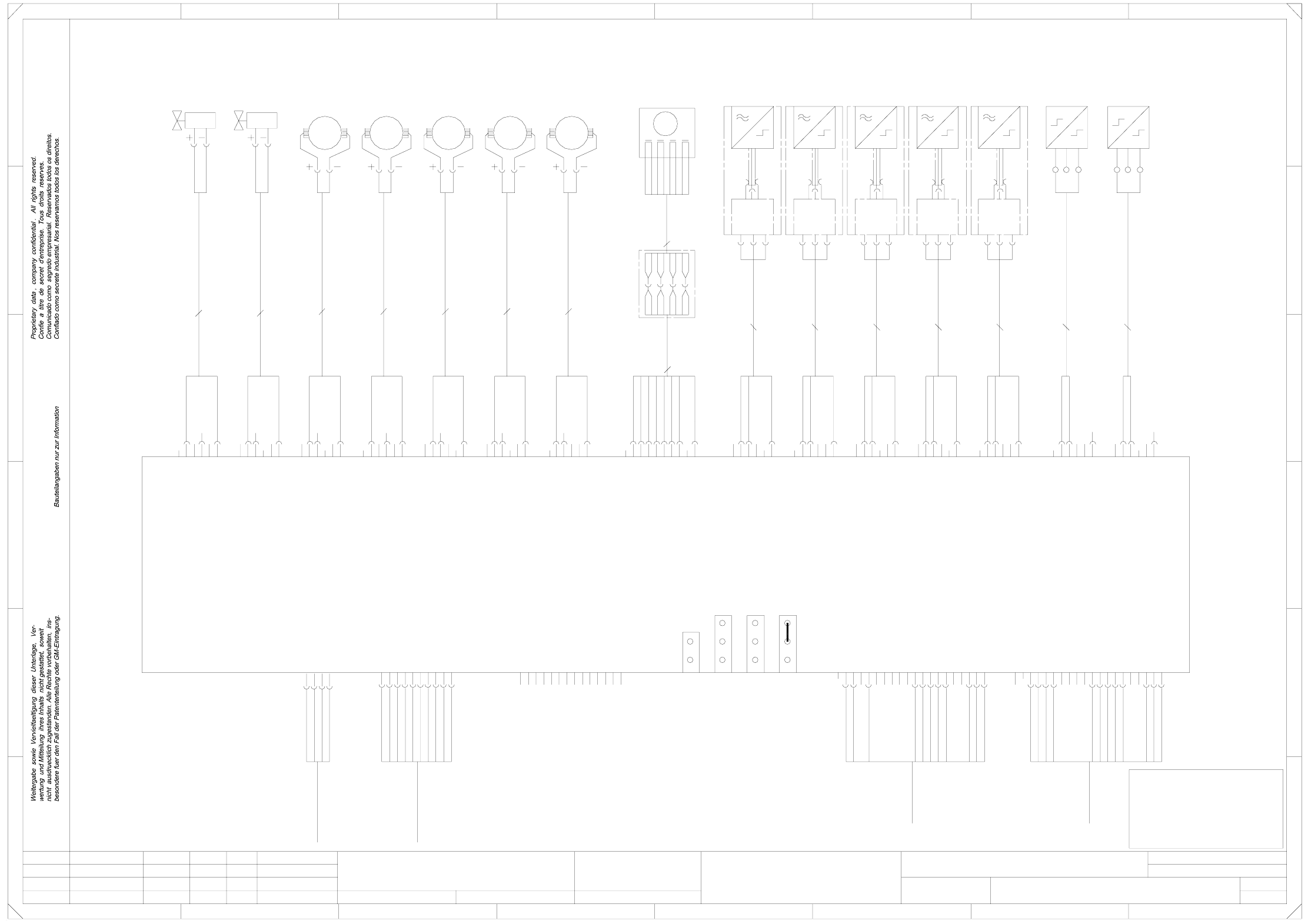
00334490-010201LD3 Conveyor module PCB1 (ao), conveyor 1, TSP100 (Sh. 2 of 5)
Status DateModified Name Stand. Orig. Replacement for Replaced by
Author
Date
Check.
Sheet
Sh.
2 x 0,25mm²
2 x 0,25mm²
2 x 0,34mm²
2 x 0,34mm²
2 x 0,34mm²
2 x 0,34mm²
2 x 0,34mm²
3X0,34mm²
3X0,34mm²
3X0,34mm²
3X0,34mm²
3X0,34mm²
3X0,25mm²
3X0,25mm²
Conveyor 2, open
Conveyor 1, jumper inserted
TSP100
00329219
Preceding machine
Interface, coding
Succeeding machine
Interface, coding
=
SIEMENS AG
+
PLEASE NOTE!
In case of modifications
this document will not
be replaced!
ye
bl
bn
bk
bl
bn
bk
bl
Cable: motor,
(conveyor 1)
X3ao
bk
wh
machine
supply
4
A1_1
00332500
A2_1
00332501
A3_1
00332502
bl
width adjustment,
wider
IF preceding
machine
00342657
00342657
IF succeeding
345678
A
B
C
D
00332504
00337726
F
A4_1
00332503
A5_1
00337726
00337726
00337726
00337726
11
12
pk
gy
(conveyor 1)
bn
wh
(conveyor 1)
bn
wh
M
_
3
1
S
L-
L+
S
L-
L+
S
L-
(conveyor 1)
bn
L-
(conveyor 1)
input conveyor
placement section 1
bn
wh
M
_
Cable: motor,
bn
X14_1b
ceramic subst.
1234 78
12
n.c.
n.c.
n.c.
n.c.
n.c.
n.c.
n.c.
n.c.
n.c.
n.c.
E
F
P_Transferred
E
D
C
B
A
gn
bn
Cable: motor,
2
5
4
3
1
4
Cable, sonar prox.sw.
(conveyor 1)
Cable, sonar prox.sw.
(conveyor 1)
Cable, sonar prox.sw.
L+
S
L+
S
L-
L+
Screening
Screening
Screening
Screening
narrower
Key
56
Key
Key
P_FaultSignal
S_FaultSignal
14
17
20
19
18
3
2
1
6
5
P_Arrived
P_Permission
10
P_Request
P_GND
S_+24VDC
S_SMEMA
S_GND_24VDC
S_FaultSignal
S_GND
S_Arrived
S_GND_24VDC
X30ao
X31ao
X32ao
Cable: motor,
(conveyor 1)
(conveyor 1)
Sonar prox. sw.,
center conveyor
Sonar prox. sw.,
placement
Sonar prox. sw.,
output conveyor
X33ao
3
2
1
(conveyor 1)
14
Cable, sonar prox.sw.
(conveyor 1)
00332505
4
Screening
n.c.
n.c.
wh
bn
wh
bn
M
_
16
15
placem. section 1
B3_1
(conveyor 1)
center conveyor
B4_1
section 2
(conveyor 1)
placem. section 2
4
7
(conveyor 1)
9
8
13
12
11
16
15
14
S_Permission
S_Transferred
S_Request
18
X35ao
X2ao
X1ao
2
1
Sonar prox. sw.,
placement
Key
bn
X11ao
Cable: motor,
00332525
wh
M1_1
M
_
Power
11
section 4
13
12
Programming
interface
3
2
1
6
2
1
4
10
9
8
13
B2_1
section 1
(conveyor 1)
2
1
6
5
4
7
10
9
8
Key
B5_1
X24ao
output conveyor
X14_1a
X15_1b
X15_1a
X16_1b
X16_1a
X17_1b
17
20
19
Limit switch, width adjustment
narrower (conveyor 1)
Dummy contact
Dummy contact
bn
X9ao
(conveyor 1)wh
width adjustment
(conveyor 1)
Sonar prox. sw.,
input conveyor
(conveyor 1)
Limit switch,
(conveyor 1)
M4_1
placement
Cable, sonar prox.sw.
(conveyor 1)
Motor,
input conveyor
(conveyor 1)
Motor,
Motor,
Motor,
Motor,
5
4
7
X10ao
00332526
wh
00335323
X34ao
3
24V
O
0V
24V
O
0V
24V
O
0V
bn
not used
00332506
Cable: valve, ceramic
00336098
Z4_1
Valve,
ceramic subst.
centering 3
(conveyor 1)wh
X17_1a
X18_1b
X18_1a
X25ao
00336099
Z5_1
Valve,
center conveyor
(conveyor 1)
output conveyor
(conveyor 1)
I
0V
24V
I
0V
3
2
1
6
5
width adjustment,
(conveyor 1)
I
input conveyor
Limit switch, width adjustment
wider (conveyor 1)
3
2
1
6
5
Motor,
Key bn
9
8
CAN bus
125kbit/s
0V
24V
O
0V
1
6
5
4
3
2
1
6
5
4
1
00332511
00332514
00332513
00332510
00332508
M2_1 M3_1 M5_1
Key
bn
S2_1
placement
section 3
(conveyor 1)
24V
I
0V
24V
5
4
3
2
1
6
5
4
3
2
4
24V
5
0V
24V
I
0V
24V
I
0V
24V
4
7
10
O
0V
24V
O
5
4
3
2
P3/5
P3/6
P2/0
P2/1
P2/2
P2/3
P2/4
P5/6
P5/7
3
2
bn
6
5
4
3
2
1
6
5
M6_1
B1_1 S1_1
1
6
5
4
3
2
1
6
X16ao
Conveyor control PCB1 (ao)
3
2
1
6
5
4
3
2
1
6
centering 4
4
3
2
1
6
5
4
9
O
0V
24V
3
2
1
6
bk
bl
5
4
plug X1ao
00335234
(conveyor 1)
bn
wh
substrate centering 1
Cable: valve, ceramic
(conveyor 1)
SMEMA standard 2-3
wh
8-wired
P5/8
P5/9
24V
I
0V
P2/15
4
3
2
Key
Key
X14ao
bk
bl
bn
X8ao
00332528
wh
bn
X7ao
00332529
wh
Cable: motor,
center conveyor
placement section 2
output conveyor
P24V
00332515
00343134
bn
wh
M
_
8
7
10
substrate centering 2
width
wh
Key
Limit switch,
To
plug X2ao
To
4
3
1
X27ao
Error loop
Siemens standard 1-2
SMEMA standard 2-3
Siemens standard 1-2
8-wired
M
_
1
6
5
4
3
2
P5/4
P5/5
4
Key
1
rd
00332527
wh
Key
bn
Reset
CANL
-
bn
br/wh
or
or/wh
rd
rd/wh
ye
ye/wh
P5V
ye/wh
P30V
M
M
M
n.c.
n.c.
n.c.
n.c.
n.c.
n.c.
4
3
1
4
3
1
rd
adjustment
Motor, width
(conveyor 1)
adjustment
2
3
X17ao
X15ao
Key
Key
Key
6
00343135
bn
Key
bn
Key
X18ao
X12ao
wh
1
6
5
rd/wh
bn
X13ao
wh
X147
P_GND_24VDC
B
P_FaultSignal
P_SMEMA
P_+24VDC
P_GND_24VDC
CANH
-
+
wh
bn
gn
ye
gy
pk
bl
A
+
A
-
B
+
-
+
n.c.
n.c.
n.c.
Leh
Leh
Leh
01
02
01
11.02.98
11.02.98
11.02.98
11.02.98
Haas
#
Conveyor module PCB1 (ao)
00334490-010201LD3
Key
bn
or
br/wh
or/wh
rd
ye
PL EA1 E
Function status
Product status
Doc. status
SMD Placement System SIPLACE HS50
(conveyor 1)
not used
not used
not used
not used
not used
not used
2 Circuit Diagrams 67
00334490-010201LD3 SLIO module PCB2 (an), conveyor 2, TSP100 (Sh. 3 of 5)
n.c.
n.c.
n.c.
n.c.
+24V
+24V
bl
+24V
GND
+5V
+5V
GND
+5V
GND
GND
GND
bk
bl
bn
0V
24V
24V
0V
24V
0V
34
0V
Prox. switch: lift. table 3 down
(conveyor2)
Prox. switch: lift. table 3 up
Cable: valve for stopper
(conveyor 2)
(conveyor 2)
(conveyor 2)
Cable: valve for stopper
bk
(conveyor 2)
(conveyor 2)
(conveyor 2)
ceramic substr. 4
X19am
X20am
X21am
X22am
X23am
bl
bn
bk
bl
bn
wh
bn
gn
CANL
CAN ground
n.c.
B
A
CANR
bn
wh
bn
wh
bn
wh
bn
bk
125kbit/s
bn
bk
bl
bn
bk
bl
bn
7
10
9
8
Voltage supply
A
+
-
0V
24V
Prox. switch: lift. table 4 up
bl
bn
bk
bl
bn
bk
bl
bn
section 3
bl
bn
bk
bl
bn
bk
bl
bn
bk
additional
Z3_2
Valve
(conveyor 2)
stopper
X14_2 X15_2
wh
wh
bn
Reset
CAN ground
bl
6
5
4
7
10
9
8
CAN bus
00336434
00335323
X17an
3
2
1
6
5
4
Proximity switch
lifting table 3
down
(conveyor 2)
Proximity switch
00333592
Control signals, PCB conveyor
(W2) lifting table motors
Control signals, PCB conveyor
(W2) lifting table motors
X18an
A
bk
stopper
placement
(conveyor 2)
section 4
Proximity switch
stopper
placement
(conveyor 2)
24V
Valve
stopper
placement
(conveyor 2)
section 3
Proximity switch
stopper
excess length
(conveyor 2)
placement section 4
00336087
00336093
00336084
00336085
excess length
additional
Proximity switch
adjustment
position
(conveyor 2)
wh
bn
1
B10_2 Z1_2 B11_2 Z2_2 B12_2 B13_2 B14_2 B15_2
0V
00336435
Proximity switch
lifting table 4
down
(conveyor 2)
Proximity switch
lifting table 4
up
(conveyor 2)
0V
24V
24V
O
I
lifting table 3
up
(conveyor 2)
Proximity switch
stopper
placement
3
2
Valve
I
0V
24V
24V
O
I
0V
24V
I
O
I
0V
0V
(conveyor2)
Prox. switch: stopper for plcmt section 4
O
I
0V
0V
24V
00336097
00336096
00336092
00336090
00336086
B6_2
width
Proximity switch
B9_2
24V
O
I
0V
24V
24V
O
I
5
24V
24V
O
I
0V
0V
24V
O
I
1
6
5
4
3
0V
24V
24V
O
I
0V
(conveyor 2)
section 4
O
24V
24V
O
I
0V
24V
24V
O
1
0V
24V
3
2
1
6
5
4
24V
3
2
1
6
5
O
I
0V
24V
24V
O
B7_2 B8_2
0V
1
6
5
4
3
2
1
6
not used
4
3
2
1
6
5
4
3
2
4
3
2
1
6
2
1
6
5
4
24V
0V
24V
0V
3
2
1
6
5
4
3
2
Key
6
5
4
3
2
1
6
5
4
X4an
X5an
Key
X7an
Key
4
3
2
1
6
5
I
0V
2
Key
Key
Key
Key
not used
X8an
not used
X10an
3
X3an
X6an
X12an
X16an
3
2
1
6
5
PORT
PORT 9
PORT
PORT
5
4
Key
3
2
1
O
I
4
PORT 13
PORT
PORT
14
15
16PORT
12
Key
Key
Key
Key
00343228
00343230
00343231
X1an
X2an
6
5
4
3
2
X9an
X11an
Key
X13an
X14an
X15an
4
3
Key
6
5
4
PORT 1
PORT
PORT
2
bk
4PORT
PORT 5
PORT
PORT
6
7
8
bl
bn
Prox. switch: lift. table 4 down
(conveyor2)
+
-
A
+
-
6
5
0V
=
SIEMENS AG
+
PLEASE NOTE
This document will
not be replaced in case
of modifications!
+24V
GND
GND
0V
24V
not used
not used
not used
24V
0V
0V
24V
0V
5
3
12
678
A
B
C
D
(conveyor 2)
5678
12345
Coding
CAN bus
addresses
CAN bus
End
E
FF
E
D
C
10
11
14
PORT
24V
O
I
0V
SLIO module PCB2 (an)
3
2
1
(conveyor 2)
ceramic
centering 3
substrate
Prox. switch for add. stopper
Proximity switch: position
(conveyor2)
retracted (conveyor 2)
(conveyor 2)
Prox. switch: stopper for plcmt
section 3 retracted
Key
Key
1
excess length
width adjustment
Cable: Proximity switch
00343229
00318137
00318137
00333592
bl
bn
bk
bn
bk
bl
bn
bk
+
-
X8_2 X9_2
00336082
00336083
00343239
00343239
bk
bl
bn
A
+
-
A
+
-
SLIO conveyor
00335233
11
-
X6_2 X7_2
00336080
00336081
13
12
ceramic substr. 3
Cable: Proximity switch
ceramic
centering 4
(conveyor 2)
substrate
Proximity switch
A
+
-
A
placement section 3
excess length
Cable: valve for add. stopper
00343239
00343239
bk
bl
bn
bk
bl
bn
Leh
Leh
Leh
01
02
01
11.02.98
11.02.98
11.02.98
11.02.98
Haas
#
SLIO module PCB 2 (an) (conveyor 2)
00334490-010201LD3
bk
bl
bn
A
+
PL EA1 E
Function status
Product status
Doc. status
SMD Placement System SIPLACE HS50
+
A
-
+
A
-
Status DateModified Name Stand. Orig. Replacement for Replaced by
Author
Date
Check.
Sheet
Sh.
3 X 0,14mm²
3 X 0,14mm²
3 X 0,14mm²
3 X 0,14mm²
3 X 0,14mm²
2 x 0,25mm²
3 X 0,14mm²
2 x 0,25mm²
3 X 0,14mm²
2 x 0,25mm²
3 X 0,14mm²
3 X 0,14mm²
3 X 0,14mm²
TSP100
2 Circuit Diagrams 68
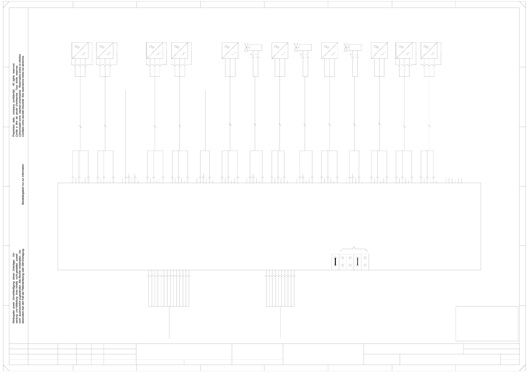
00334490-010201LD3 Conveyor module PCB2 (ap), conveyor 2, TSP100 (Sh. 4 of 5)
X12ap
wh
bn
X13ap
wh
bn
Key
Key
Key
bn
2
1
6
5
4
3
3
2
1
6
5
4
24V
2
1
6
I
0V
24V
I
1
6
5
4
3
2
M
versorgung
4
1
6
5
1
6
5
4
9
8
0V
24V
O
0V
24V
O
0V
4
3
2
24V
O
0V
24V
3
2
1
6
5
4
Key
Key
Key
Conveyor control PCB2 (ap)
3
2
3
2
1
6
5
4
S1_2 S2_2
placement
section 4
(conveyor 2)
buffer conveyor
(conveyor 2)
I
0V
24V
width
(conveyor 2)
Sonar
proximity switch
0V
3
2
1
6
5
1
6
5
1
6
5
0V
24V
I
0V
24V
O
CAN bus
125kBit/s
00335323
X34ap
3
2
24V
O
0V
4
7
10
9
O
0V
24V
O
0V
3
2
1
X15ap
X17ap
3
00336112
00336111
M2_2 M3_2 M5_2 B1_2
ceramic substrate
centering 3
(conveyor 2)
wh
Key
bn
X11ap
output conveyor
(conveyor 2)
adjustment
M4_2
placement
section 3
(conveyor 2)
input
(conveyor 2)
conveyor
Limit switch
(conveyor 2)
width adjustment
4
24V
I
4
3
2
5
4
7
10
9
8
bn
X8ap
00336106
wh
Key bn
X7ap
1
6
5
X3ap
bk
bl
bn
8
Key
bn
not used
X24ap
00336101
00336110
00336113
6
5
4
Key
bn
X25ap
00336102
Z5_2
Valve
B5_2
output
(conveyor 2)
conveyor
X14_2a
X15_2b
X15_2a
00336103
wh
M1_2
X17_2a
X18_2b
X18_2a
not used
Motor
input conveyor
(conveyor 2)
Motor
Motor
Motor
(conveyor 2)
X30ap
3
0V
24V
I
wh
bn
X9ap
00336105
wh
Key
Programming
interface
3
2
1
6
5
00336107
wh
Key
9
8
13
12 bk
bl
bn
bk
bl
bn
Z4_2
Valve
ceramic substrate
00336109
00336120
00336119
buffer conveyor
(conveyor 2)
B4_2
placement
(conveyor 2)
section 4
13
12
11
16
15
14
17
X16_2b
X16_2a
X17_2b
X35ap
X2ap
X1ap
narrower
not used
Sonar
proximity switch
Sonar
proximity switch
Sonar
Motor
Motor
Key
2
1
6
1
Strom-
11
14
13
12
00336117
A5_2
00336118
00337726
00337726
00337726
00337726
4
7
10
br/wh
or/wh
rd
ye
11
16
15
14
17
20
X14_2b
B2_2
placement
centering 4
(conveyor 2)
wh
5
4
7
10
9
8
(conveyor 2)
Cable: sonar prox. switch
(conveyor 2)
20
19
18
Cable: sonar prox. switch
(conveyor 2)
Limit switch
width adjustment
wider
IF preceding
machine
00342658
proximity switch
Sonar
proximity switch
bn
X10ap
00336104
00336114
A2_2
00336115
A3_2
00336116
A4_2
bn
wh
bn
P3/5
P3/6
P2/0
P2/1
00337726
bn
or
L+
S
L-
L+
rd/wh
ye/wh
To
plug X2ap
To
plug X1ap
19
18
3
(conveyor 2)
section 4
B3_2
Cable: sonar prox. switch
input conveyor
plcmt section 4
buffer conveyor
plcmt section 3
output conveyor
n.c.
n.c.
n.c.
n.c.
n.c.
n.c.
n.c.
Cable: sonar prox. switch
(conveyor 2)
n.c.
M6_2
not used
not used
Cable: sonar prox. switch
(conveyor 2)
Limit switch for width
adjustment wider (conveyor 2)
Limit switch for width
00342658
IF suceeding
machine
X33ap
3
2
4
2
1
4
wh
A
B
C
D
E
FF
L+
S
L-
Cable: valve for ceramic substrate
E
S
L-
L+
screen
screen
screen
00335234
Cable: valve for ceramic substrate
Cable: Motor
2
1
6
n.c.
n.c.
n.c.
n.c.
n.c.
n.c.
1234 8
12
n.c.
n.c.
n.c.
SMEMA standard 2-3
not used
not used
not used
not used
=
SIEMENS AG
+
PLEASE NOTE
This document will
not be replaced in case
of modifications !
wh
(conveyor 2)
input conveyor
placement section 4
bn
wh
2
1
6
5
4
Key
3
wh
centering 3
(conveyor 2)
5
4
3
2
0V
Key
Key
X14ap
bk
bl
bn
X16ap
4
3
2
4
24V
I
7
10
3
2
1
6
5
bl
bn
Key
1
6
5
4
bk
X18ap
adjustment narrower (conveyor 2)
2
1
_
Cable: Motor
M
345678
A1_2
M
_
00336108
(conveyor 2)
bn
wh
centering 4
S_Arrived
D
C
B
A
screen
screen
n.c.
S_Permission
S_Transferred
S_Request
5
4
n.c.
n.c.
n.c.
SMEMA standard 2-3
Reset
X31ap
X32ap
X27ap
Error loop
Siemens standard 1-2
3
4
Key
Key
Siemens standard 1-2
Cable: Motor
(conveyor 2)
bn
wh
567
3
1
4
(conveyor 2)
M
_
buffer conveyor
placement section 3
output conveyor
P_GND_24VDC
P_Arrived
P_Permission
P_Transferred
P_Request
P_GND
S_+24VDC
S_SMEMA
S_GND_24VDC
S_FaultSignal
+
-
+
-
S_GND_24VDC
P2/2
P2/3
P2/4
P5/5
P5V
P24V
P30V
M
M
_
Cable: Motor
L-
S
L+
L-
S
1
bl
rd
00343136
width
P_FaultSignal
S_FaultSignal
4
3
1
4
M
_
Cable: Motor
bn
3
1
P_GND_24VDC
P_+24VDC
P_SMEMA
P_FaultSignal
bn
or
br/wh
or/wh
rd
ye
rd/wh
ye/wh
A
+
A
-
B
8-pole
+
adjustment
Motor for width
(conveyor 1)
adjustment
P5/6
P5/7
P5/8
P5/9
P2/15
P5/4
_
M
wh
bn
(conveyor 2)
wh
bn
(conveyor 2)
or
or/wh
rd
rd/wh
ye
ye/wh
8-pole
00343137
X148
Cable: motor
(conveyor 1)
B
-
bn
br/wh
M
CANH
CANL
3
1
4
11.02.98
01
02
01
Leh
Leh
Leh
wh
bn
gn
ye
gy
pk
PL EA1 E
00334490-010201LD3
Conveyor module PCB2 (ap)
#
Haas
11.02.98
11.02.98
11.02.98
Function status
Product status
Doc. status
SMD Placement System SIPLACE HS50
(conveyor 2)
Status Modified NameDate Stand. Orig. Replacement for Replaced by
Author
Date
Check.
Sheet
Sh.
2 x 0,25mm²
2 x 0,25mm²
2 x 0,34mm²
2 x 0,34mm²
2 x 0,34mm²
2 x 0,34mm²
2 x 0,34mm²
3X0,34mm²
3X0,34mm²
3X0,34mm²
3X0,34mm²
3X0,34mm²
3X0,25mm²
3X0,25mm²
00329219
TSP100
Conveyor 1, jumper inserted
Conveyor 2, open
Interface, coding
Preceding machine
Interface, coding
Succeeding machine