00193161-01.pdf - 第45页
Manual S-20/S-23 HM/S-25 HM/F4/F5 HM /HS-50 Placement of 0402 components 03/2001 edition 45 5 Component feeders for 0402 component s 5.1 T ypes of f eeder 5.1.1 8 mm S II f eeder Fig. 5 - 1 8 mm S II feeder Articl e numb…
Placement of 0402 components Manual S-20/S-23 HM/S-25 HM/F4/F5 HM/HS-50
03/2001 edition
44
4.4 Nozzles
Å Have the nozzle magazines been filled correctly for the current set-up?
Å Has a reference run been carried out to check the vacuum values and height offset values?
Å Have the ceramic nozzles been cleaned as described in the job guide?
Å Were the nozzles checked afterwards?
Å Are the nozzle suction surfaces undamaged?
Å Has nozzle scanning been activated, if required?
4.5 Components
Å Who is the manufacturer?
Å Have the mechanical and electrical tolerances been observed?
Å Was a quality check carried out, and has it been certified?
Å Are the leads or connection surfaces of the component in good condition (corrosion, tinning,
shape)?
4.6 Other points to note
Make sure that the component is picked up by the nozzle as centrally as possible. If the
component is set down on the solder pad, it is much less likely that the nozzle will be contaminated
by surplus solder paste. You can prevent the components being picked up off-center by
– regularly using a vacuum cleaner to clean the feeder supporting surface on the component
table, thus ensuring that the feeder lies flat.
– carefully moving the component table into the machine and locking it in place.
– activating feeder position recognition, if possible.
– only replacing the nozzles on the Collect & Place heads manually in exceptional
circumstances, and generally picking up automatically from the nozzle magazines.
– activating nozzle scanning, if possible.
– scanning the nozzles at regular intervals and replacing dirty nozzles.
– using a PCB support so that the PCB does not sag during placement.
– keeping to and not increasing the GF tolerances.
Manual S-20/S-23 HM/S-25 HM/F4/F5 HM/HS-50 Placement of 0402 components
03/2001 edition
45
5 Component feeders for 0402 components
5.1 Types of feeder
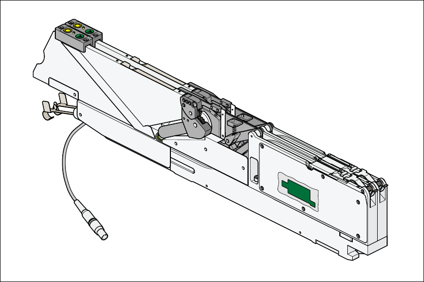
5.1.1 8mm S II feeder
Fig. 5 - 1 8mm S II feeder
Article number 00141096-xx
Width 30mm
Tracks per feeder 2
Maximum number of feeders 2 x 20 (S/F); 4 x 12 (HS-50)
Stock of components for 7” reels approx. 10,000 – 15,000
Reel diameter 7" - 15" (max. 381mm)
Transport pitch (variable) 2mm / 4mm
Cycle time 60ms
Power supply 30 V-
Placement of 0402 components Manual S-20/S-23 HM/S-25 HM/F4/F5 HM/HS-50
03/2001 edition
46
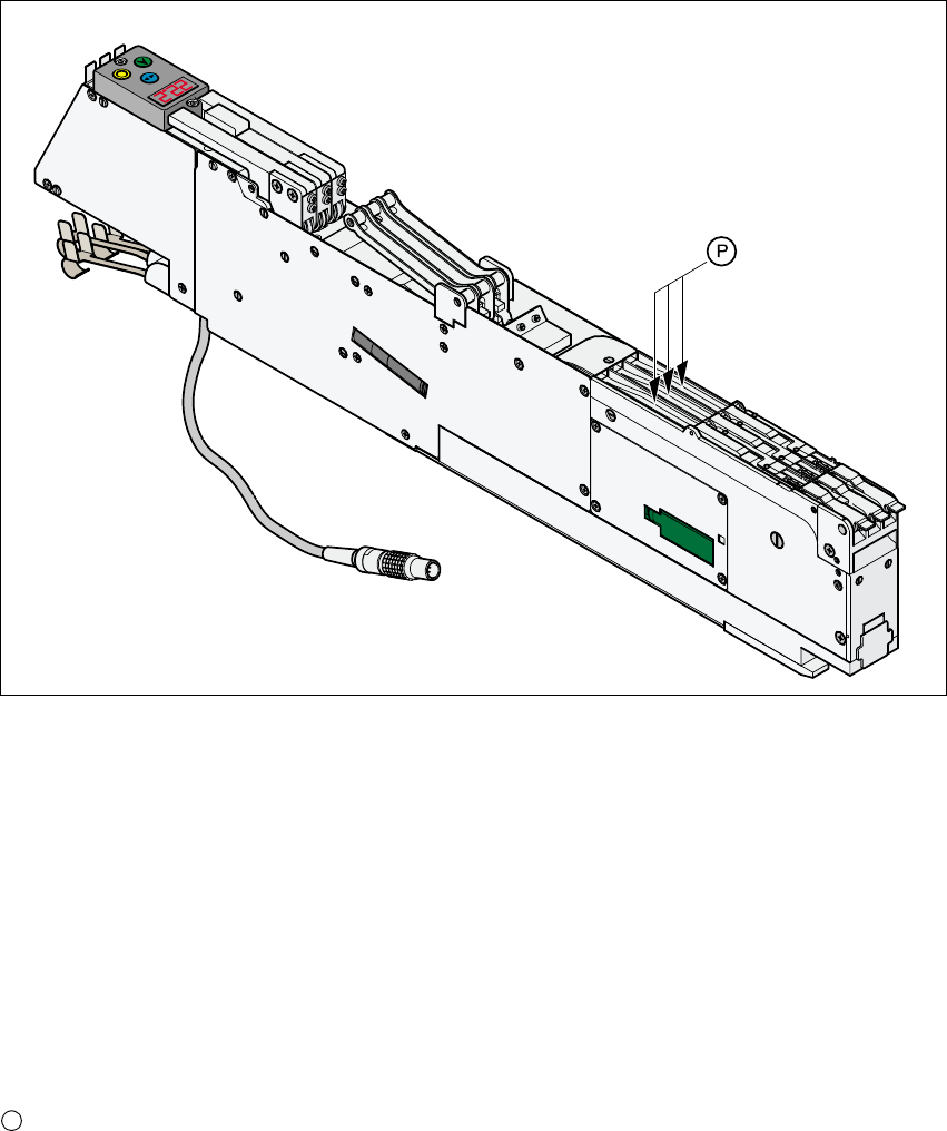
5.1.2 3 x 8mm S feeder
Fig. 5 - 2 3 x 8mm S feeder
Article number 00141098-xx
Width 30mm
Tracks per feeder 3
Maximum number of feeders 2 x 20 (S/F); 4 x 12 (HS-50)
Stock of components for 7” reels approx. 10,000 – 15,000
Reel diameter 7" - 15" (max. 381mm)
Transport pitch (variable) 2mm / 4mm
Cycle time 60ms
Power supply 30 V-
Park position for the 0402 tape spacer
P