00193161-01.pdf - 第64页
Placement of 0 402 components Manual S-20/S-23 HM/S-25 HM/F4/F5 HM/HS-50 03/2001 edition 64 8.3 Checki ng the ‘ SIZE ’ and ‘ LEAD ’ measuring mode p arameters Å From the ‘ T est Comp onent ’ m enu, cl ick on the ‘ Me asu…
Manual S-20/S-23 HM/S-25 HM/F4/F5 HM/HS-50 Placement of 0402 components
03/2001 edition
63
8.2 Checking the contrast sensitivity
Å Click on the ‘Table …’ button.
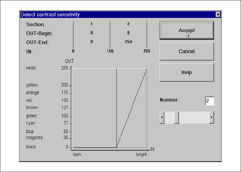
The ‘Contrast Sensitivity’ selection box appears.
Fig. 8 - 4 ‘Contrast Sensitivity’ selection box
The contrast sensitivity values and curve should correspond to those shown in the diagram
above. If this is not the case, modify the values. 8
Placement of 0402 components Manual S-20/S-23 HM/S-25 HM/F4/F5 HM/HS-50
03/2001 edition
64
8.3 Checking the ‘SIZE’ and ‘LEAD’ measuring mode parameters
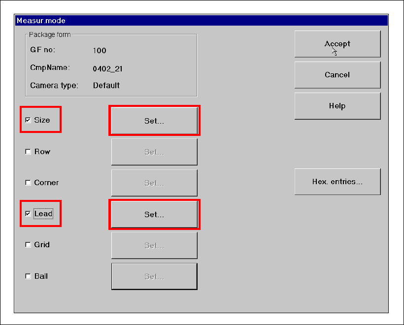
Å From the ‘Test Component’ menu, click on the ‘Measuring Mode’ icon. The ‘Measuring Mode’
menu appears. The ‘Size’ and ‘Lead’ check boxes must be checked. All the others should be
left unchecked.
Fig. 8 - 5 ‘Measuring Mode’ menu
Manual S-20/S-23 HM/S-25 HM/F4/F5 HM/HS-50 Placement of 0402 components
03/2001 edition
65
8.3.1 Parameters for ‘SIZE’ measuring mode
PLEASE NOTE:
Only the ‘Size’ and ‘Lead’ check boxes must be checked in the Measuring Mode menu. The ‘Row’,
‘Corner’, ‘Grid’ and ‘Ball’ measuring modes must NOT be checked. 8
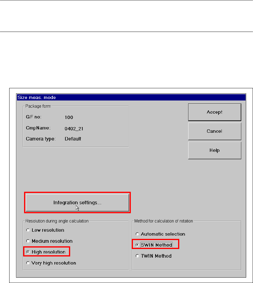
Å Click on the ‘Set…’ button. The 'Size measuring mode' window opens.
Settings:
Resolution for angle calculation high resolution
Method for calculation of rotation SWIN method 8
Fig. 8 - 6 Setting ‘Size’ measuring mode