00193161-01.pdf - 第69页
Manual S-20/S-23 HM/S-25 HM/F4/F5 HM /HS-50 Placement of 0402 components 03/2001 edition 69 The error ‘ Compon ent le ngth outside t olerance ’ occasi onally occurs with 0402 compo nents. This is gener ally caus ed by di…
Placement of 0402 components Manual S-20/S-23 HM/S-25 HM/F4/F5 HM/HS-50
03/2001 edition
68
8.3.3 Checking the hex values
Å From the ‘Measuring Mode’ menu (see Fig. 8 - 5 on page 64), click on the ‘Hex entries ...’
button.
ATTENTION: 8
Only people with sufficient technical knowledge should change the parameters shown in Fig.
8 - 9. 8
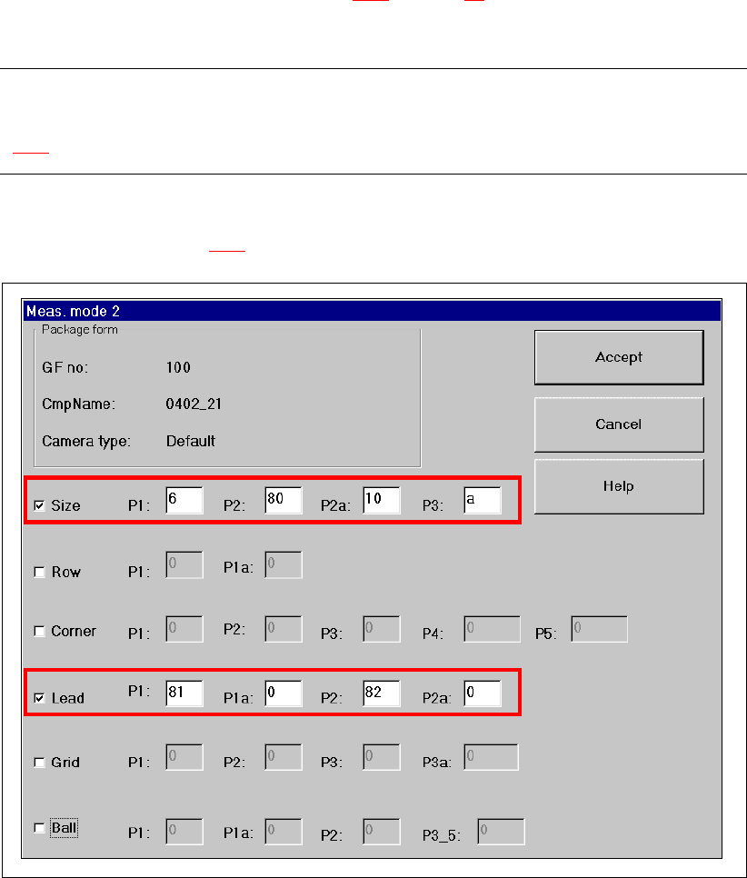
Only the ‘Size’ and ‘Lead’ check boxes must be checked in the ‘Measuring Mode 2’ menu. The
parameters shown in Fig. 8 - 9
must be entered. 8
Fig. 8 - 9 Measuring Mode 2 – Default setting
Manual S-20/S-23 HM/S-25 HM/F4/F5 HM/HS-50 Placement of 0402 components
03/2001 edition
69
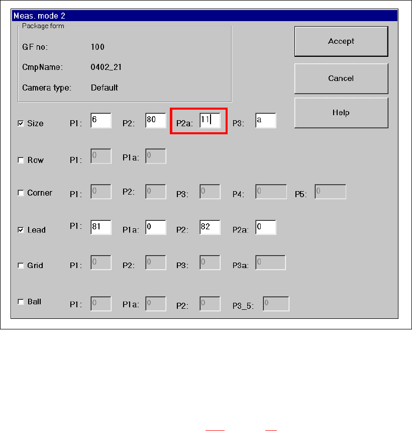
The error ‘Component length outside tolerance’ occasionally occurs with 0402 components. This
is generally caused by dirty nozzles.
It can also occasionally occur with 0402 components with a dark body and very narrow leads,
even though the nozzles are clean. In this case, you should change parameter P2a under ‘Size’
from 10 to 11.
Fig. 8 - 10 Measuring Mode 2 – Size mode parameter P2a modified
8.4 Checking the lead dimensions
Å From the ‘Test Component’ menu (see Fig. 8 - 3 on page 62), click on the ‘Lead Dimensions>’
button. The ‘Lead Dimensions’ video image appears, together with the parameters.
Å Check the set values
– optical length: 0.95 mm (up to 1 mm is possible)
– optical width: 0.45 mm (up to 0.5 mm is possible)
Å Press ESC to exit the ‘Lead Dimensions’ option.

Placement of 0402 components Manual S-20/S-23 HM/S-25 HM/F4/F5 HM/HS-50
03/2001 edition
70
8.5 Checking the illumination values
Å From the ‘Test Component’ menu (see Fig. 8 - 3 on page 62), click on the ‘Illumination’ button.
The ‘Illumination’ video image appears.
Å Use the ‘tab’ key to select the illumination level.
The brightness is displayed for each level. The values should be as follows:
Å Press ‘ESC’ to exit the ‘Illumination’ option and return to the main view.
9 Solder paste application
9.1 Mask printing
During solder paste printing with metal stencils, all the solder is deposited on a PCB in a single
pass. The solder paste is thoroughly mixed, and then ‘rolled’ over the metal stencil with the pattern
to be printed using a squeegee. The motion of the squeegee presses solder paste through the
apertures in the stencil and onto the PCB below.
9.2 Properties of the stencil
Å Use a laser-cut stainless steel stencil for placing 0402 components, and note the following rule
of thumb for the shape of the apertures:
9
9
9
9
9
9
9
9
Fig. 9 - 1 Rule of thumb for the shape of the apertures
Illumination level Brightness
flat 120
average 100
steep 120