192277 - Micron Technical Reference Volume 3 - 第103页
INTERCHANGEABLE UNDER SCREEN CLEANER MODULE ADJUSTMENTS AND SETTINGS Chapter Issue 6, Jan 17 Technical Reference Manual 25.9 10. If adjustment is not required, go to Step 14. 1 1. Move the cleaner towards the rear of the…
INTERCHANGEABLE UNDER SCREEN CLEANER MODULE
ADJUSTMENTS AND SETTINGS
25.8 Technical Reference Manual Chapter Issue 6, Jan 17
ADJUSTMENTS AND SETTINGS
CAUTION
PRINT MEDIUM AND SOLVENTS. WHEN USING OR HANDLING ANY PRINT
MEDIUM OR SOLVENT FORMULATION THE MANUFACTURERS’ SAFETY DATA
SHEETS MUST BE STRICTLY ADHERED TO.
MANDATORY
TOXIC CHEMICALS MAY BE PRESENT. SAFETY GLOVES MUST BE WORN.
MANDATORY
TOXIC CHEMICALS MAY BE PRESENT. EYE PROTECTION MUST BE WORN.
Screen Cleaner
Home
1. Select Maintenance.
2. Select Diagnostics.
3. Use Next or Previous to highlight Screen Cleaner.
4. Select Select Module.
5. Use Next or Previous to highlight Toggle Screen Cleaner Home Clamp.
6. Select Run Diagnost to release the electromagnetic clamps.
7. Move the cleaner by hand towards the rear of the machine until the error
message ‘Screen Cleaner Out Of Position’ is displayed.
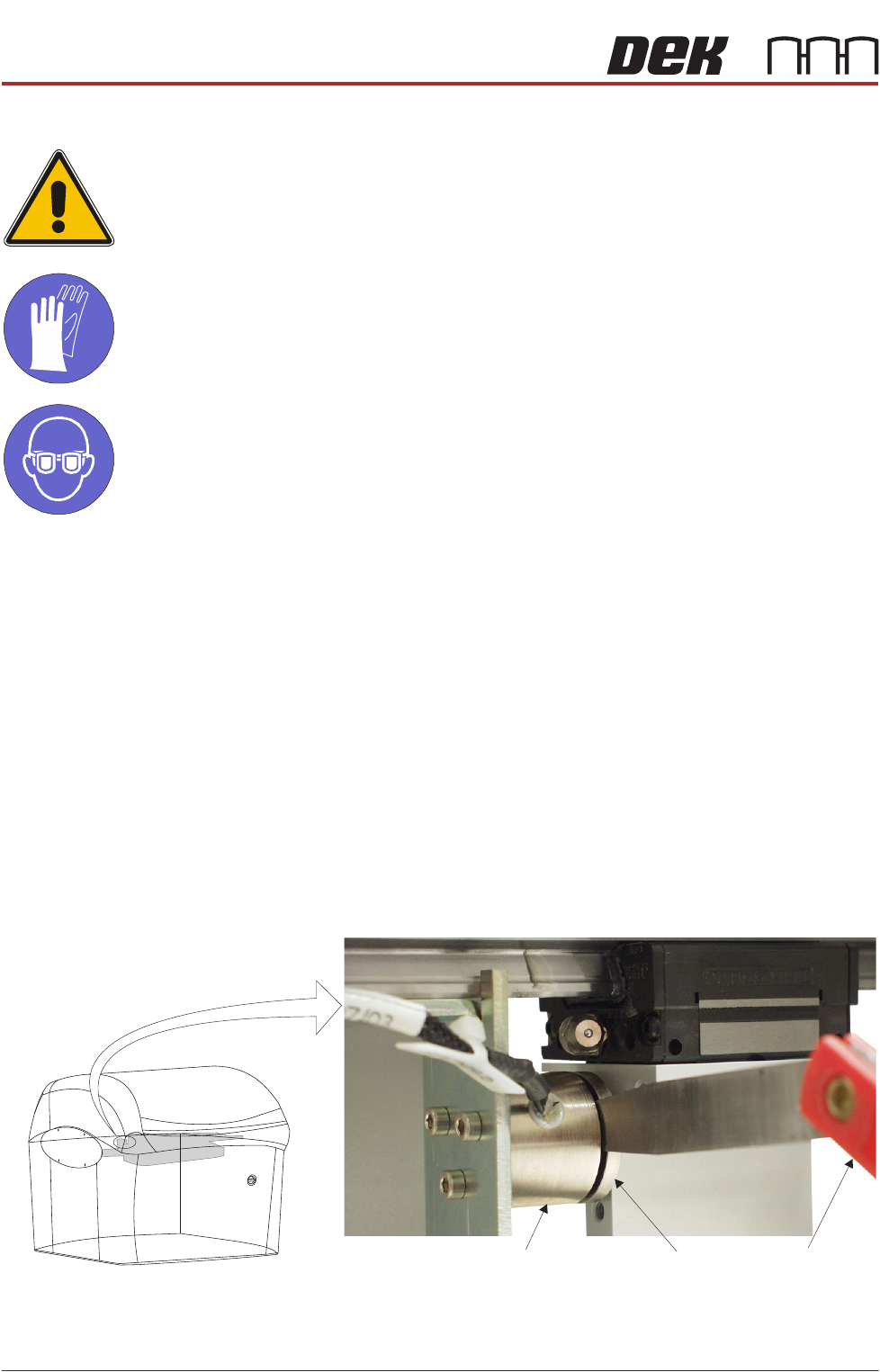
8. Using a 2.0mm feeler gauge positioned between the left hand screen
cleaner home electromagnetic clamp (8SOL19) and the clamp plate, pull the
cleaner towards the front of the machine. With the clamp plate held lightly
against the feeler gauge, ensure that the error message remains displayed.
9. Repeat Step 8 using a 1.5mm feeler gauge, ensure the error message has
extinguished.
View on Front of Machine
Feeler GaugesElectromagnetic Clamp
Clamp Plate
INTERCHANGEABLE UNDER SCREEN CLEANER MODULE
ADJUSTMENTS AND SETTINGS
Chapter Issue 6, Jan 17 Technical Reference Manual 25.9
10. If adjustment is not required, go to Step 14.
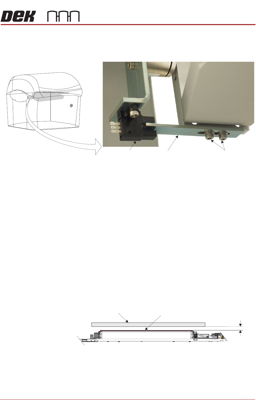
11. Move the cleaner towards the rear of the machine until the vane securing
screws are accessible.
12. Loosen the vane securing screws, adjust the vane and re-tighten the
securing screws.
13. Repeat Steps 8 to 10.
14. Select Run Diagnost to energise the electromagnetic clamps.
15. Select Exit.
16. Select Exit.
17. Select Back.
Screen Cleaner
Height Adjustment
1. Select Unload Screen.
2. Open the front printhead cover.
3. Remove the screen from the machine.
4. Using the calibration screen, position the front edge of the screen frame over
the under screen cleaner wipers.
5. Using feeler gauges ensure the gap between squeegee wipers and the
screen frame is 3.25mm ±0.25mm.
6. If adjustment is not required, go to Step 11.
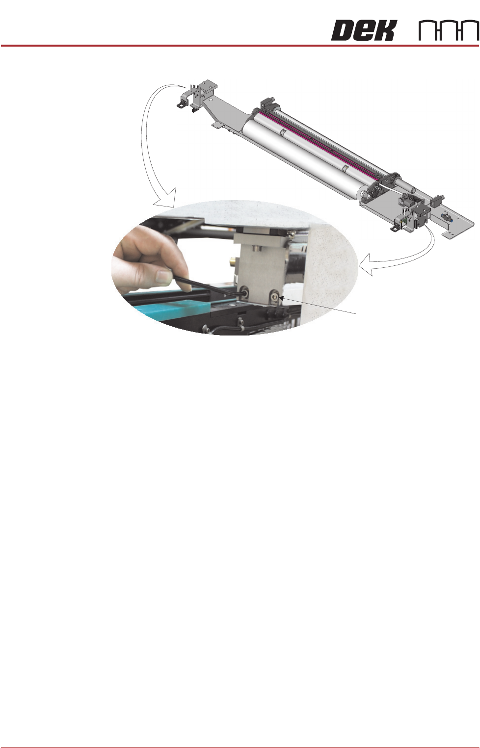
7. To gain access to cleaner securing screws move the underscreen cleaner
away from its home position.
View on Front of Machine
Vane Securing Screws
Home Sensor
Vane
Screen Frame
3.25mm
±0.25mm
Squeegee Wiper Assembly
View on Front of Machine
INTERCHANGEABLE UNDER SCREEN CLEANER MODULE
ADJUSTMENTS AND SETTINGS
25.10 Technical Reference Manual Chapter Issue 6, Jan 17
8. Loosen the two securing screws at either end of the cleaner tray.
9. Adjust the cleaner tray until the correct gap between the wipers and stencil
is achieved.
10. Tighten the securing screws and recheck the gap between the wipers and
screen frame.
11. Remove the calibration screen and refit the product screen.
12. Close the front printhead cover.
13. Press the System button.
14. Select Load Screen.
Securing Screw
(in 4 positions)