192277 - Micron Technical Reference Volume 3 - 第118页
CYCLONE UNDER STENCIL CLEANER MODULE ADJUSTMENTS AND SETTINGS 26.8 Technical Reference Manual Chapter Issue 11, Feb 18 hand cleaner pickup magnet (A) . 2. Measure from the rear face of the cleaner tray to th e rear face …
CYCLONE UNDER STENCIL CLEANER MODULE
ADJUSTMENTS AND SETTINGS
Chapter Issue 11, Feb 18 Technical Reference Manual 26.7
ADJUSTMENTS AND SETTINGS
WARNING
STRONG MAGNET FIELD. A STRONG MAGNETIC FIELD EXISTS IN THE
VICINITY OF THIS LABEL. THIS MAY PRESENT A HAZARD TO PERSONNEL OR
EQUIPMENT.
))
((
PROHIBITION
ELECTROMAGNETIC FIELD. AN ELECTROMAGNETIC FIELD EXISTS WITHIN
THE MACHINE FROM THE LINEAR MOTORS. THESE MAY PRESENT A HAZARD
TO PEOPLE FITTED WITH AN IMPLANTED CARDIAC DEVICE. THE MOTOR
MANUFACTURER RECOMMENDS A SAFE DISTANCE OF AT LEAST 15MM.
PROHIBITION
ELECTROMAGNETIC FIELD. AN ELECTROMAGNETIC FIELD EXISTS WITHIN
THE MACHINE FROM THE LINEAR MOTORS. THESE MAY PRESENT A HAZARD
TO PEOPLE FITTED WITH AN IMPLANTED CARDIAC DEVICE. THE MOTOR
MANUFACTURER RECOMMENDS A SAFE DISTANCE OF AT LEAST 15MM.
PROHIBITION
STRONG MAGNETIC FIELD. A STRONG MAGNETIC FIELD EXISTS IN THE
VICINITY OF THE LINEAR MOTORS THAT REPRESENT A SERIOUS HAZARD TO
PEOPLE FITTED WITH METALLIC IMPLANTS.
PROHIBITION
STRONG MAGNETIC FIELD. A STRONG MAGNETIC FIELD EXISTS IN THE
VICINITY OF THE LINEAR MOTORS THAT MAY ACT UPON FERROUS OBJECTS
WHOSE MOVEMENTS COULD LEAD TO PERSONAL INJURY AND/OR DAMAGE
TO THE MACHINE.
CAUTION
PRINT MEDIUM AND SOLVENTS. WHEN USING OR HANDLING ANY PRINT
MEDIUM OR SOLVENT FORMULATION THE MANUFACTURERS’ SAFETY DATA
SHEETS MUST BE STRICTLY ADHERED TO.
MANDATORY
TOXIC CHEMICALS MAY BE PRESENT. SAFETY GLOVES MUST BE WORN.
MANDATORY
TOXIC CHEMICALS MAY BE PRESENT. EYE PROTECTION MUST BE WORN.
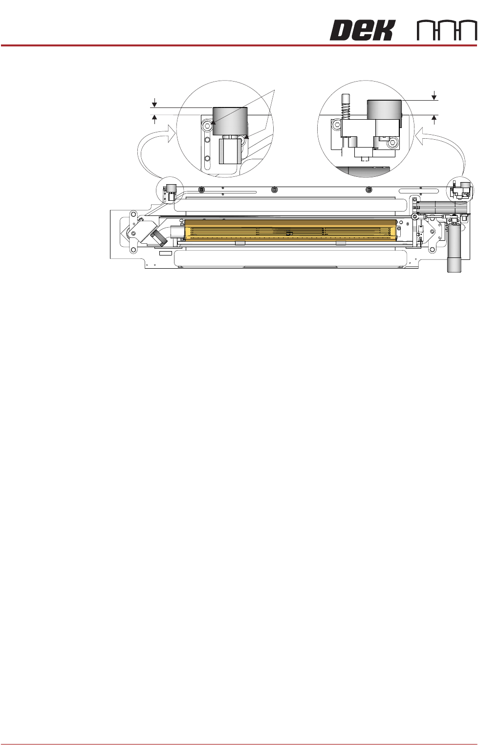
Cleaner Pickup
Magnet
The right hand cleaner pickup magnet is positionally fixed. The left hand cleaner
pickup magnet is adjustable and must be set to the same dimension as the right
hand side magnet.
NOTE
The left hand side cleaner pickup magnet is factory set and should not need
adjustment unless replaced due to a fault.
To check and adjust the left hand cleaner pickup magnet, use the following
procedure:
1. Measure from the rear face of the cleaner tray to the rear face of the right
CYCLONE UNDER STENCIL CLEANER MODULE
ADJUSTMENTS AND SETTINGS
26.8 Technical Reference Manual Chapter Issue 11, Feb 18
hand cleaner pickup magnet (A).
2. Measure from the rear face of the cleaner tray to the rear face of the left
hand cleaner pickup magnet (B).
3. Ensure that B is 5.2mm (±0.5mm) less than A.
4. If adjustment is required, loosen the two left hand cleaner pickup magnet
securing screws using a 3mm Allen key.
5. Adjust the magnet to achieve the dimension in Step 3.
6. Tighten the two securing screws loosened in Step 4.
7. Recheck the measurement.
Stencil Cleaner
To Camera
Parallelism
The stencil cleaner to camera parallelism adjustment ensures that the two
cleaner pickup magnets and the cleaner tray are aligned to the camera beam.
NOTE
The cleaner pickup magnets must be parallel to the camera beam.
1. Remove the printer front cover and side safety covers.
NOTE
Engineers should be aware of the implications of operating the printer when
covers have been removed.
2. Open the printhead front cover.
3. Remove the stencil (if fitted).
4. Ensure that the stencil cleaner is pulled toward the front of the printer.
5. Close the printhead front cover.
6. Power up the printer.
7. Select Diagnostics.
8. Press the System button.
9. Use Next or Previous to highlight Screen Cleaner.
10. Select Select Module.
11. Use Next or Previous to highlight Toggle Cleaner Camera Clamp.
Plan View on Cyclone Cleaner
Securing
Screws
A
B
CYCLONE UNDER STENCIL CLEANER MODULE
ADJUSTMENTS AND SETTINGS
Chapter Issue 11, Feb 18 Technical Reference Manual 26.9
12. Select Run Diagnost to release the electromagnetic clamps.
13. Use Next or Previous to highlight Toggle Cleaner Home Clamp.
14. Select Run Diagnost to release the electromagnetic clamps.
15. Select Exit.
16. Use Next or Previous to highlight Camera Axes.
17. Select Select Module.
18. Ensure Home Camera X Axis is highlighted.
19. Select Run Diagnost.
20. Use Next to highlight Home Camera Y Axis.
21. Select Run Diagnost.
22. Use Next or Previous to highlight Drive to Reference Position.
23. Select Run Diagnost.
24. Select Exit.
25. Press the E-Stop button.
26. Open the printhead front cover.
27. Manually move the cleaner away from the home position.
28. Ensure that the two pickup magnets (left and right) engage with camera
beam at the same time.
NOTE
Due to the spring on the cleaner attached sensor, the camera beam must
be held stationary and the cleaner is moved to it.
29. If no adjustment required, go to Step 45.
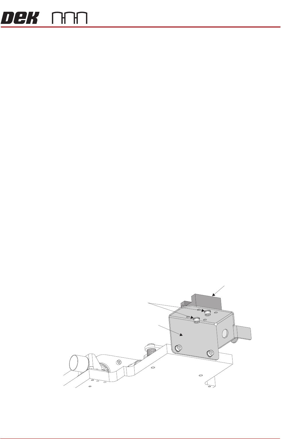
30. Loosen the camera Y bearing securing screws, on both ends of the camera
tray.
31. Swivel the cleaner tray to align the pickup magnets to the camera beam;
taking care not to disturb the camera position.
32. Recheck the magnet alignment to that of camera beam. The front faces of
the magnets should be parallel to the camera axis linear bearing.
View on Rear Left
Linear Bearing Block
Securing Screws
Cleaner Tray Bracket