192277 - Micron Technical Reference Volume 3 - 第120页
CYCLONE UNDER STENCIL CLEANER MODULE ADJUSTMENTS AND SETTINGS 26.10 Technical Reference Manual Chapter Issue 11, Feb 18 33. T ighten the four securing screws. 34. Re-check the alignment. 35. Remove the four securing scre…
CYCLONE UNDER STENCIL CLEANER MODULE
ADJUSTMENTS AND SETTINGS
Chapter Issue 11, Feb 18 Technical Reference Manual 26.9
12. Select Run Diagnost to release the electromagnetic clamps.
13. Use Next or Previous to highlight Toggle Cleaner Home Clamp.
14. Select Run Diagnost to release the electromagnetic clamps.
15. Select Exit.
16. Use Next or Previous to highlight Camera Axes.
17. Select Select Module.
18. Ensure Home Camera X Axis is highlighted.
19. Select Run Diagnost.
20. Use Next to highlight Home Camera Y Axis.
21. Select Run Diagnost.
22. Use Next or Previous to highlight Drive to Reference Position.
23. Select Run Diagnost.
24. Select Exit.
25. Press the E-Stop button.
26. Open the printhead front cover.
27. Manually move the cleaner away from the home position.
28. Ensure that the two pickup magnets (left and right) engage with camera
beam at the same time.
NOTE
Due to the spring on the cleaner attached sensor, the camera beam must
be held stationary and the cleaner is moved to it.
29. If no adjustment required, go to Step 45.
30. Loosen the camera Y bearing securing screws, on both ends of the camera
tray.
31. Swivel the cleaner tray to align the pickup magnets to the camera beam;
taking care not to disturb the camera position.
32. Recheck the magnet alignment to that of camera beam. The front faces of
the magnets should be parallel to the camera axis linear bearing.
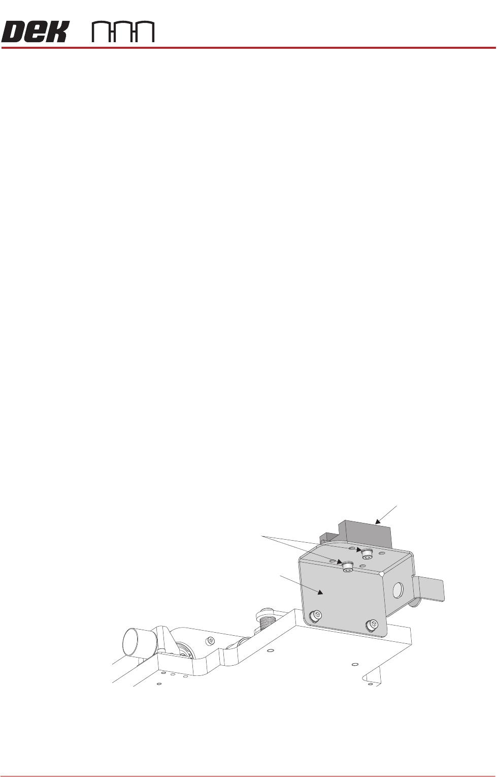
View on Rear Left
Linear Bearing Block
Securing Screws
Cleaner Tray Bracket
CYCLONE UNDER STENCIL CLEANER MODULE
ADJUSTMENTS AND SETTINGS
26.10 Technical Reference Manual Chapter Issue 11, Feb 18
33. Tighten the four securing screws.
34. Re-check the alignment.
35. Remove the four securing screws one at a time and refit using a suitable
thread locking compound.
36. Close the printhead front cover.
37. Reset the E-Stop button.
38. Press the System button.
39. Use Next or Previous to highlight Camera Axes.
40. Select Select Module.
41. Use Next to highlight Home Camera Y Axis.
42. Select Run Diagnost.
43. Use Next to highlight Home Camera X Axis.
44. Select Run Diagnost.
45. Select Exit.
46. Select Exit.
47. Select Back.
48. Open the printhead front cover.
49. Refit the printer front cover.
50. Close the printhead front cover.
51. Refit the side safety covers.
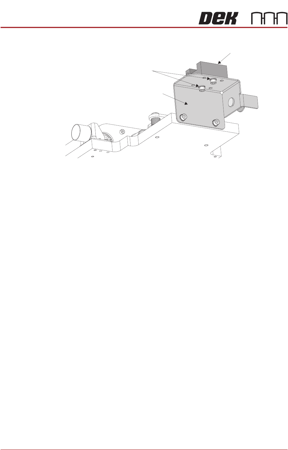
View on Rear Left
Linear Bearing Block
Securing Screws
Cleaner Tray Bracket

CYCLONE UNDER STENCIL CLEANER MODULE
ADJUSTMENTS AND SETTINGS
Chapter Issue 11, Feb 18 Technical Reference Manual 26.11
Stencil Cleaner
Height and
Parallelism
The stencil cleaner height, X and Y parallelism are factory set using a special
jig and should not be adjusted. In the event of adjustment being required,
contact your local CSG office.