192277 - Micron Technical Reference Volume 3 - 第126页
CYCLONE UNDER STENCIL CLEANER MODULE REPLACEMENT PROCEDURES 26.16 Technical Reference Manual Chapter Issue 11, Feb 18 Solvent Pump 1. Make sure that the printer is clear of boards. 2. In Diagnostics select Rising T able …
CYCLONE UNDER STENCIL CLEANER MODULE
REPLACEMENT PROCEDURES
Chapter Issue 11, Feb 18 Technical Reference Manual 26.15
14. Place the appropriate sized vacuum chamber on the oscillating bracket and
connect the vacuum hose.
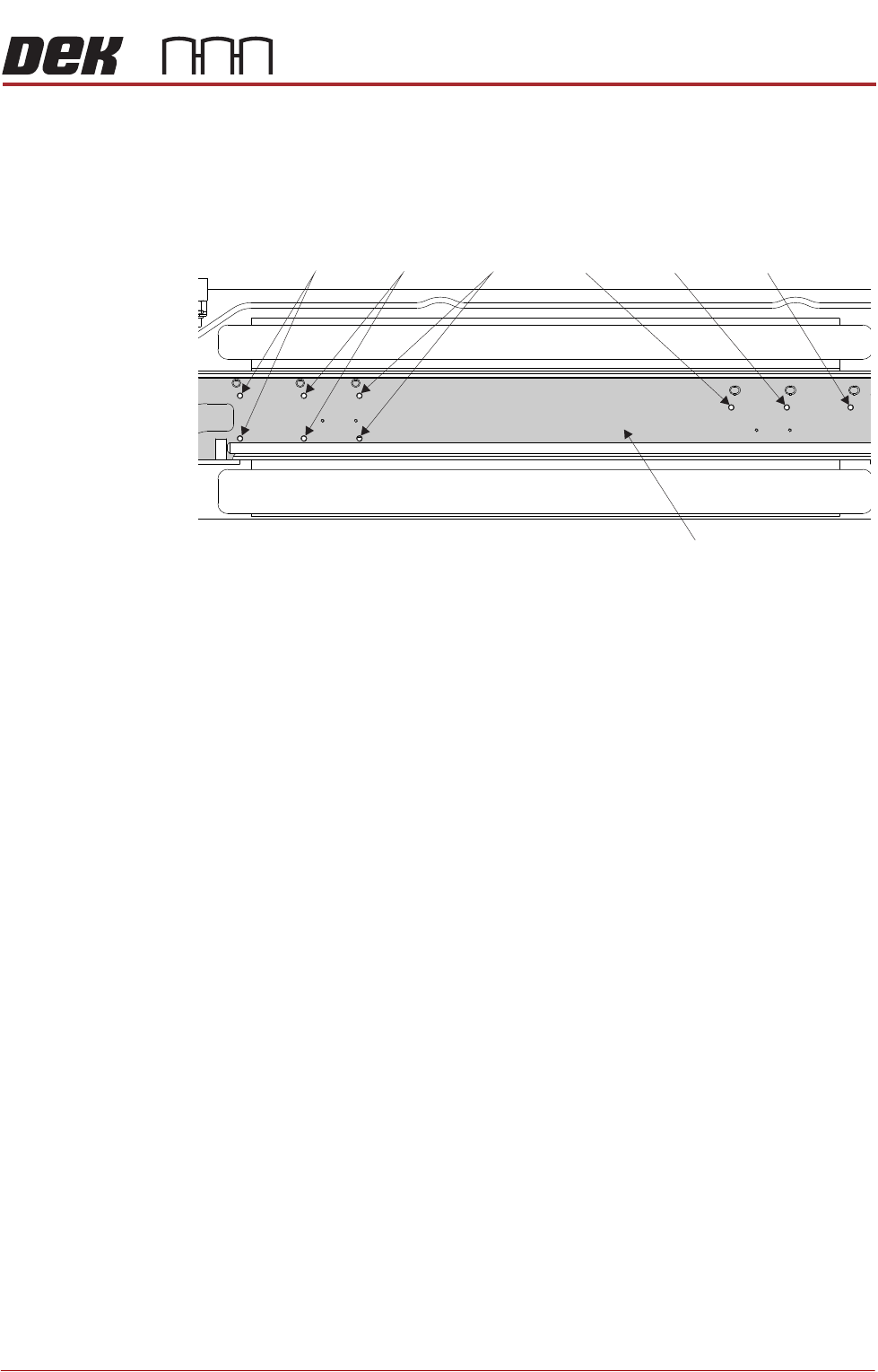
15. Using the graphic below, align the vacuum chamber to the appropriate set
of holes.
16. Refit the three securing screws.
17. Connect the solvent tube from the vacuum chamber to the in-line connector.
18. Fit the correct size fabric cassette with a fabric roll fitted.
19. Close the printhead cover.
20. Power up the machine and press the System button when prompted.
21. Select Open Cover Commands.
22. Open the front printhead cover.
23. Select Prime Solvent.
24. When prompted, press the two control buttons simultaneously ensuring that
the solvent is wetting the fabric above the vacuum chamber.
25. If fabric counting is disabled, go to Step 29.
26. Select Change Paper.
27. Ensure the fabric length parameter matches that stated on the fabric roll
wrapper.
28. Select Continue.
29. Select Prime Paper.
30. When prompted, press the two control buttons simultaneously ensuring that
the fabric feeds correctly and any slack is taken up.
31. Refit the stencil.
32. Close the front printhead cover.
33. Press the System button.
34. Select Load Screen.
35. Select Back.
Plan View on Cyclone Cleaner
515mm 400mm 300mm 300mm 400mm 515mm
Oscillating Bracket

CYCLONE UNDER STENCIL CLEANER MODULE
REPLACEMENT PROCEDURES
26.16 Technical Reference Manual Chapter Issue 11, Feb 18
Solvent Pump 1. Make sure that the printer is clear of boards.
2. In Diagnostics select Rising Table.
3. Select Select Module.
4. Using the Next/Previous buttons, select Home Rising Table.
5. Select Exit.
6. Turn the printer’s power off and lock the mains isolator.
7. Open the front printhead cover and place the board clamp setting plate,
centrally in the tooling area and on top of the rails.
NOTE
This is used to support the cleaner and protect the board clamps.
8. Manually move the cleaner from its home position so that it is centrally above
the setting plate.
9. Disconnect the vacuum arm inlet and stow it safely away.
10. Undo the M3 x 6 socket cap head screw and remove the securing bracket
to the solvent pump.
11. Disconnect the 4mm solvent feed tube.
12. Disconnect the multi-way connector in the right hand bracket housing.
13. Unscrew the three screws, using a crosshead screwdriver, which secure the
pump to the bracket.
14. Remove and replace the solvent pump.
15. Fit the pump to the bracket using the crosshead screws.
16. Reconnect the multi-way connector.
17. Fit the solvent feed tubing.
18. Refit the bracket to the cleaner unit.
19. Pull the cleaner to the front of the printer.
20. Ensure that no tooling has been left in the printer. Leave the setting plate in
place.

CYCLONE UNDER STENCIL CLEANER MODULE
REPLACEMENT PROCEDURES
Chapter Issue 11, Feb 18 Technical Reference Manual 26.17
21. Close the printhead front cover.
22. Remove the lock from the mains lock-out.
23. Power up the printer.
24. Select Diagnostics.
25. Press the System switch.
26. Select the Camera Axes.
27. Select Home Camera X Axis and select Home Camera Y Axis to home
the camera axes.
28. Select Exit.
29. Select the Screen Cleaner module page.
30. Ensure that all functions within stencil cleaner diagnostics operate correctly
and that there are no leaks from the feed tubing.
31. Select Exit.
32. Select Exit.