192277 - Micron Technical Reference Volume 3 - 第13页
RAPID TRANSIT CONVEYOR (R TC) MODULE OVERVIEW Chapter Issue 4, Aug 14 Technical Reference Manual 22.1 CHAPTER 22 RAPID TRANS IT CONV EYOR (RTC) MODULE OVER VI EW Figure 22-1 Front V iew of RTC Rails Item Descript ion Ite…
Technical Reference Manual
CUSTOMER USE Date
Originator Name & Department
Position
Company
Telephone
Fax
Email
Machine Model Number
Software Version
Serial Number
Manual Title
Chapter
Chapter / Figure
Details of Change
Attachments
INTERNAL USE No.
Accepted No Reason
Yes Priority Immediate
Next Release
Details of Change
Manuals Affected Name
Date Signature
RAPID TRANSIT CONVEYOR (RTC) MODULE
OVERVIEW
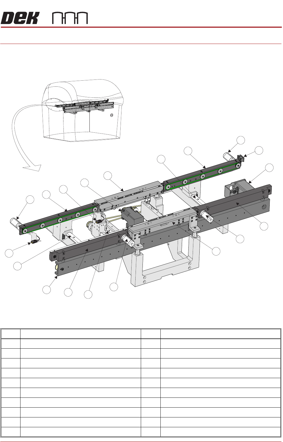
Chapter Issue 4, Aug 14 Technical Reference Manual 22.1
CHAPTER 22 RAPID TRANSIT CONVEYOR (RTC) MODULE
OVERVIEW
Figure 22-1 Front View of RTC Rails
Item Description Item Description
1 Rear Outroad Conveyor Transport Belt Motor 11 Inroad Conveyor Linear Guide
2 Outroad Board Stop 12 Board at Left Sensor
3 Board Load Servo Motor 13 Rear Inroad Conveyor Transport Belt Motor
4 Front Outroad Conveyor 14 Rear Inroad Conveyor
5 Front Outroad Conveyor Transport Belt Motor 15 Board at Stop Sensor
6 Front Print Station and Board Clamp 16 Moving Rail Stepper Motor
7 Front Inroad Conveyor Transport Belt Motor 17 Rear Print Station and Board Clamp
8 Rail Width Linear Guide (in 2 positions) 18 Outroad Conveyor Linear Guide
9 Front Inroad Conveyor 19 Rear Outroad Conveyor
10 Transport Mechanism
1
2
3
4
5
6
7
8
9
10
11
12
13
14
15
16
17
18
19
RAPID TRANSIT CONVEYOR (RTC) MODULE
OVERVIEW
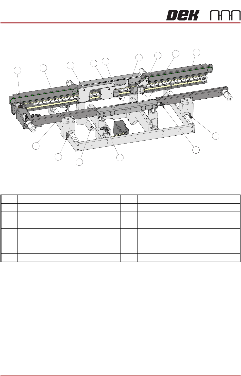
22.2 Technical Reference Manual Chapter Issue 4, Aug 14
Figure 22-2 Rear View of RTC Rails
NOTE
Information given in this manual references a machine set up for left to right feed
direction. For machines designated right to left feed direction, contact ASM
Customer Support for assistance. Right to left feed machines are not a direct
mirror of the left to right machine the following exceptions relate:
1. In the circuit diagram, later in this chapter, Node 11 becomes Node 16.
2. In the circuit diagram, motor wiring designations are mirrored.
3. The motors are wired in the single direction mode, that is, left to right or right
to left; a machine wired for one direction cannot be wired for the opposite feed
direction.
Item Description Item Description
1 Transport Mechanism Drive Belt 8 Transport Mechanism Linear Guide
2 Pneumatic Rail Width Clamp (in 2 positions) 9 Outroad Vane
3 Rail Lifted Sensor 10 Board Stop Vane
4 Moving Rail Home Sensor 11 Inroad Vane Stepper Motor
5 Moving Rail Leadscrew (in 2 positions) 12 Transport Mechanism Home Vane
6 Transport Mechanism Home Sensor 13 Inroad Vane
7 Board at Right Sensor 14 Inroad Vane Lift Solenoid
1
2
2
3
4
5
6
7
8
9
10
11
12
13
14