192277 - Micron Technical Reference Volume 3 - 第133页
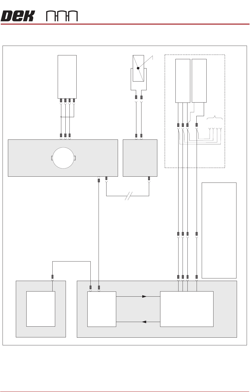
RISING TABLE MODULE - STYLE 1 ELECTRICAL SCHEMATIC Chapter Issue 9, Aug 14 Technical Reference Manual 27.3 ELECTRICAL SCHEMA TIC NextMove ES (I/O Node 1) X5 Machine Control Enclosure NextMove Interface Card X4 I/Ps O/Ps …

RISING TABLE MODULE - STYLE 1
OVERVIEW
27.2 Technical Reference Manual Chapter Issue 9, Aug 14
The rising table moves up and down within the machine supporting the product
board, via the tooling, and accurately positions the height of the rails at several
different pre-determined heights during the print cycle. The rising table contains
the attachment points for the transport rails and the drive for the moving rear
rail, for more information refer to the Transport Rails chapter.
The rising table heights, determined by the software and referenced from the
home position, are as follows:
• Home Position
• Transport Height
• Vision Height
• Print Height
The rising table homes only when the machine initialises, this is achieved at
power up or when exiting diagnostics. Transport height is preset in the product
file allowing clearance for the board to clear the tooling whilst entering and
leaving the machine. Vision height brings the board into the camera focal length
for the vision system. The board is paused at this height whilst screen alignment
is achieved. The rising table is taken up to print height for the board to be
printed.
The rising table also supports the remote board stop which is used for position-
ing large or heavy boards.
NOTE
1. Currently, there are two types of standard transport rail system: The Rail
System (RS) and the Modular Transport Rail (MTR) The rising table home
sensor is set at different heights for both types.
2. The Rapid Throughput Conveyor (RTC) printer option has its rising table
home height 10mm lower than that of a standard printer.
RISING TABLE MODULE - STYLE 1
ELECTRICAL SCHEMATIC
Chapter Issue 9, Aug 14 Technical Reference Manual 27.3
ELECTRICAL SCHEMATIC
NextMove ES
(I/O Node 1)
X5
Machine Control Enclosure
NextMove
Interface Card
X4
I/Ps O/Ps
Remote Board Stop (optional)
If Remote Board Stop is
Right Hand Side Configured
Board Stop Extended
Sensor (10SE25)
Board At Stop
Sensor (10SE26)
8SK05(L)
8SK05(R)
+12V
0V
0V
Sig
Sig
USB
M36PL11
BPL6A
BSK6
M36PL28
3PL35
Motherboard
Machine PC
NOTES
The breaks in the CAN Bus chain reflect that additional1.
I/O Nodes may be fitted, refer to Machine Control
chapter for the complete CAN Bus chain.
2. Camera Board Stop sensors are detailed in the Camera
chapter of this manual.
3. Rail Lift sensors are detailed in the respective Transport
Rails chapter of this manual.
Rising Table
Home Sensor
(8SE1)
N6 4PL
(8M1)
Rising Table Motor
Servo Node 6
CAN In
N6 3PL
M36PL35
CAN Bus
(see Note)
Main Machine
I/O Node 2
Board Stop
(16SOL14)
Manual Operation
16SK14
N2PL4
N2SK2
M
CAN Out
N6SK2
+24V
SIG
0V
(L)
RISING TABLE MODULE - STYLE 1
ADJUSTMENTS AND SETTINGS
27.4 Technical Reference Manual Chapter Issue 9, Aug 14
ADJUSTMENTS AND SETTINGS
Rising Table Home Setting
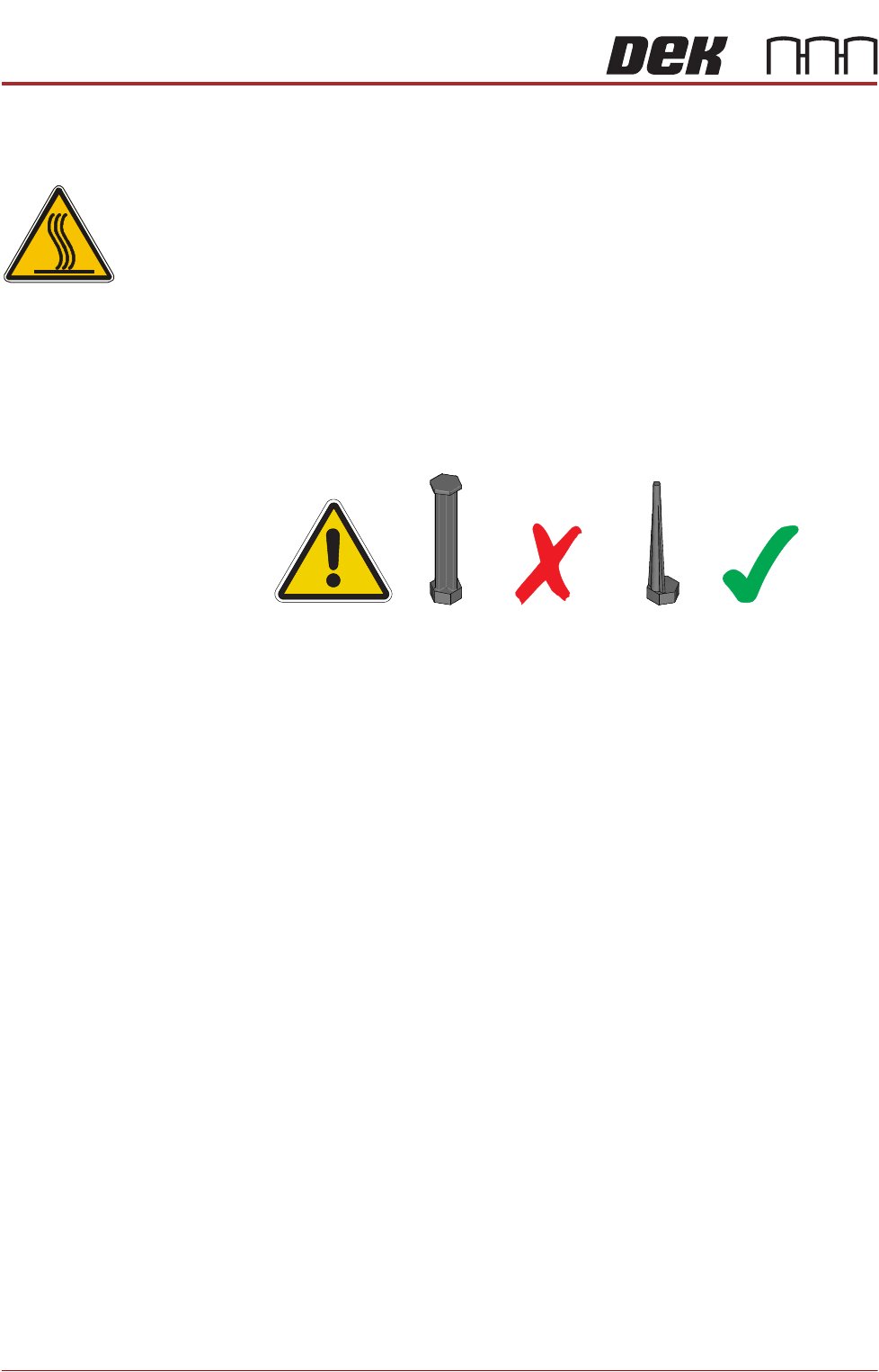
WARNING
HOT SURFACES. THE SURFACE OF THIS COMPONENT OR SURROUNDING
AREA MAY BECOME HOT DURING PROLONGED OPERATION. CARE TO BE
TAKEN WHEN WORKING IN THE VICINITY OF THIS COMPONENT.
NOTE
1. 1. For MTR rail systems, the rails are fitted with a modular mid section.
MTR rails are deeper than the RS systems. The magnetic tooling pins
supplied with RS rail systems must not be used with the MTR rail system,
as this may cause equipment damage.
2. 2. Due to the deeper rails being present on MTR systems, the rising table
height settings are different.
3. 3. For rising table home setting on a dual lane machine, refer to the Dual
Lane Module chapter.
4. The Rapid Throughput Conveyor (RTC) printer option has its rising table
home height 10mm lower than that of a standard printer (198mm to
200mm).
1. Select Open Cover Commands.
2. Select Carriage To Rear.
3. Select Unload Screen.
4. Open the front printhead cover.
5. Move the screen so that the rear edge is further forward than the rear edge
of the manual tooling plate.
6. Close the front printhead cover.
7. Press the System button.
8. Select Back.
9. Select Maintenance.
10. Select Diagnostics.
11. Use Next or Previous to highlight Screen Change.
12. Select Select Module.
13. Ensure Toggle Screen Clamps is highlighted.
14. Select Run Diagnost.
15. Select Exit.