192277 - Micron Technical Reference Volume 3 - 第137页
RISING TABLE MODULE - STYLE 1 ADJUSTMENTS AND SETTINGS Chapter Issue 9, Aug 14 Technical Reference Manual 27.7 35. Carry out the follo wing calibrations: • Vision Heigh t, Camera System Module chapter refers • Print Heig…
RISING TABLE MODULE - STYLE 1
ADJUSTMENTS AND SETTINGS
27.6 Technical Reference Manual Chapter Issue 9, Aug 14
25. From the left hand side of the machine, slacken the two home vane securing
screws.
26. If the rising table needs to be higher, move the home vane downwards and
secure the two home vane securing screws.
27. If the rising table needs to be lower, move the home vane upwards and
secure the two home vane securing screws.
28. Remove the steel rule from the machine.
29. Select Run Diagnost.
30. Repeat Steps 21 to 29.
31. Refit the safety cover.
32. Select Exit.
33. Select Exit.
34. Select Back.
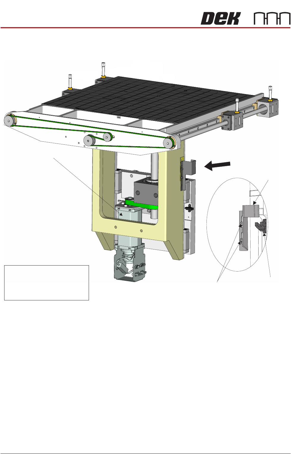
Rising Table Motor
A
View on Rear Right of Rising Table
Rising Table
Home Sensor
VaneHome
Home Vane
Securing Screws
View on Arrow A
NOTE
The rising table home position is
lower with Modular Transport Rail
system therefore, the home vane
has a smaller vane.

RISING TABLE MODULE - STYLE 1
ADJUSTMENTS AND SETTINGS
Chapter Issue 9, Aug 14 Technical Reference Manual 27.7
35. Carry out the following calibrations:
• Vision Height, Camera System Module chapter refers
• Print Height, Calibrations section of this chapter refers
RISING TABLE MODULE - STYLE 1
REPLACEMENT PROCEDURES
27.8 Technical Reference Manual Chapter Issue 9, Aug 14
REPLACEMENT PROCEDURES
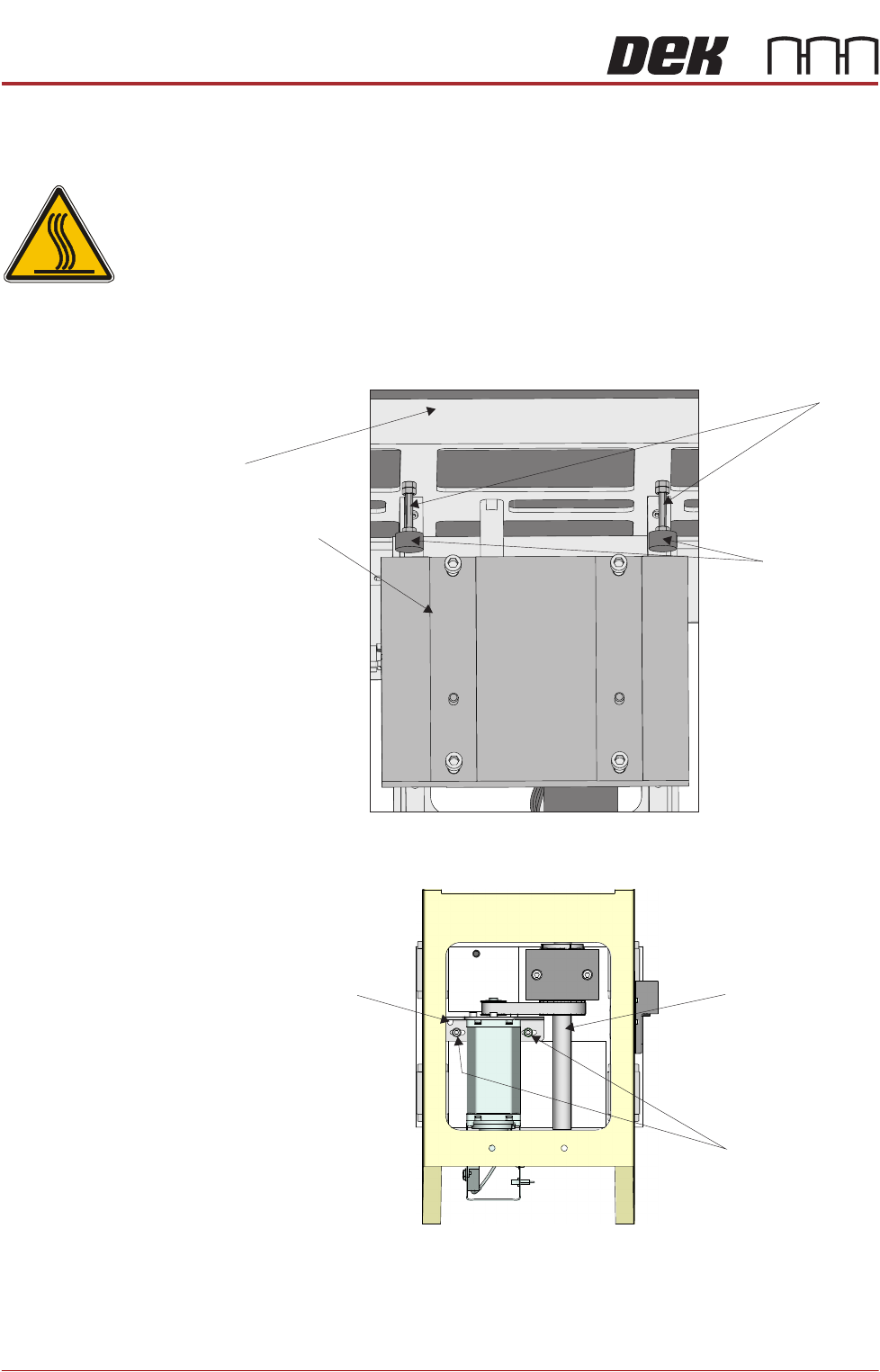
Rising Table Drive Belt
WARNING
HOT SURFACES. THE SURFACE OF THIS COMPONENT OR SURROUNDING
AREA MAY BECOME HOT DURING PROLONGED OPERATION. CARE TO BE
TAKEN WHEN WORKING IN THE VICINITY OF THIS COMPONENT.
1. Gain access to the rising table motor.
2. Slacken one of the studs and unscrew it until the rubber buffer is in contact
with the mounting plate. Tighten the stud. Do not adjust the other stud.
3. Using a 5mm Allen key, slacken the two rising table motor securing screws.
4. Slide the rising table motor towards the leadscrew to slacken the drive belt.
5. Remove the drive belt and discard.
View From Front of Rising Table Assembly
Rubber Buffer
Mounting Plate
Stud
Table
Spring Balance
Attachment Point
Leadscrew
Rising Table
Motor Securing
Screws
View From Rear of Rising Table Motor Assembly