192277 - Micron Technical Reference Volume 3 - 第139页
RISING TABLE MODULE - STYLE 1 REPLACEMENT PROCEDURES Chapter Issue 9, Aug 14 Technical Reference Manual 27.9 6. Fit the replacement drive belt. 7. Using the spring balance attachmen t point, tension the drive belt to 6kg…
RISING TABLE MODULE - STYLE 1
REPLACEMENT PROCEDURES
27.8 Technical Reference Manual Chapter Issue 9, Aug 14
REPLACEMENT PROCEDURES
Rising Table Drive Belt
WARNING
HOT SURFACES. THE SURFACE OF THIS COMPONENT OR SURROUNDING
AREA MAY BECOME HOT DURING PROLONGED OPERATION. CARE TO BE
TAKEN WHEN WORKING IN THE VICINITY OF THIS COMPONENT.
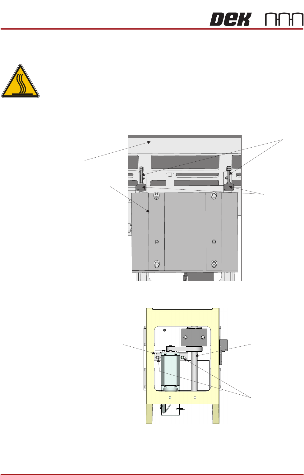
1. Gain access to the rising table motor.
2. Slacken one of the studs and unscrew it until the rubber buffer is in contact
with the mounting plate. Tighten the stud. Do not adjust the other stud.
3. Using a 5mm Allen key, slacken the two rising table motor securing screws.
4. Slide the rising table motor towards the leadscrew to slacken the drive belt.
5. Remove the drive belt and discard.
View From Front of Rising Table Assembly
Rubber Buffer
Mounting Plate
Stud
Table
Spring Balance
Attachment Point
Leadscrew
Rising Table
Motor Securing
Screws
View From Rear of Rising Table Motor Assembly
RISING TABLE MODULE - STYLE 1
REPLACEMENT PROCEDURES
Chapter Issue 9, Aug 14 Technical Reference Manual 27.9
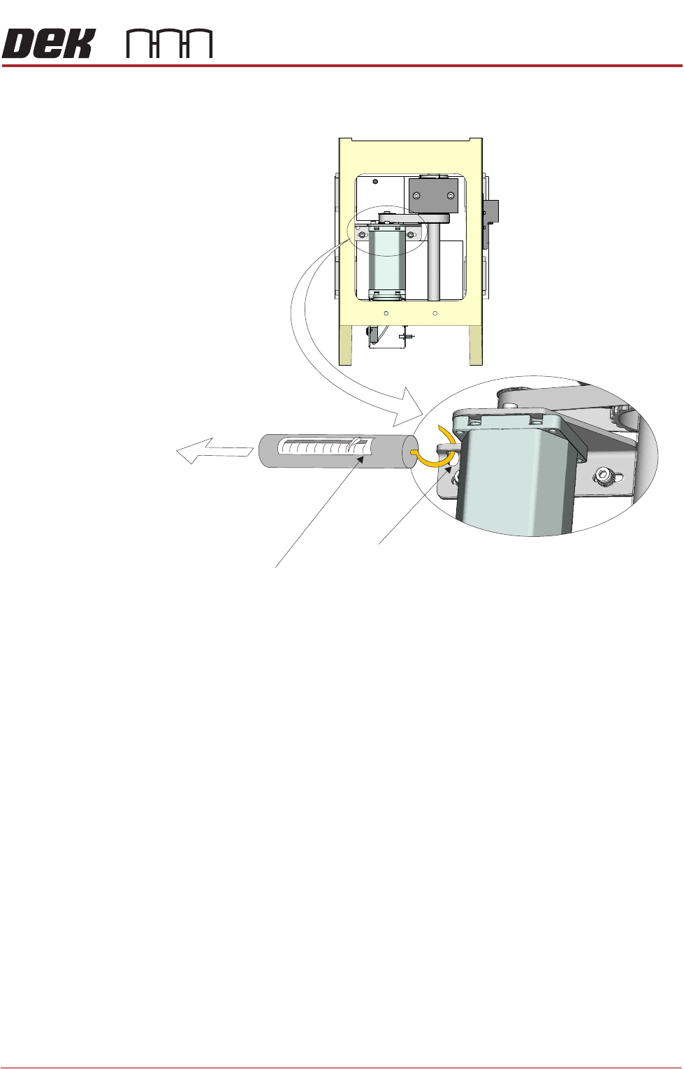
6. Fit the replacement drive belt.
7. Using the spring balance attachment point, tension the drive belt to 6kg.
8. Whilst maintaining this tension, tighten the rising table motor securing
screws.
9. Slacken the stud adjusted in Step 2 and set the height of the buffer level with
the other stud. Tighten the stud.
10. Carry out Rising Table Home Setting, Adjustments and Settings section of
this chapter refers.
View From Rear of Rising Table Motor Assembly
Spring Balance
Attachment Point
6kg
Tension
Spring Balance
RISING TABLE MODULE - STYLE 1
CALIBRATIONS
27.10 Technical Reference Manual Chapter Issue 9, Aug 14
CALIBRATIONS
Print Height Print reference height is the height to which the rising table is taken to achieve
board clamp to screen contact at zero board thickness. Print height is the height
the rising table is taken to print the product and is calculated as the print
reference height minus the board thickness and print gap. This calibration
accurately sets the board to screen ‘set contact height’ and ensures constant
print pressure is applied. Deterioration in this calibration may result in inconsist-
ent print pressure thereby effecting the print quality.
1. Ensure that a screen is fitted in the machine.
2. Select Maintenance.
3. Select Diagnostics.
4. Use Next or Previous to highlight Rising Table.
5. Select Select Module.
6. Ensure that Home Rising Table is highlighted.
7. Select Run Diagnost.
8. Use Next or Previous to highlight Set Reference Print Height.
9. Select Run Diagnost.
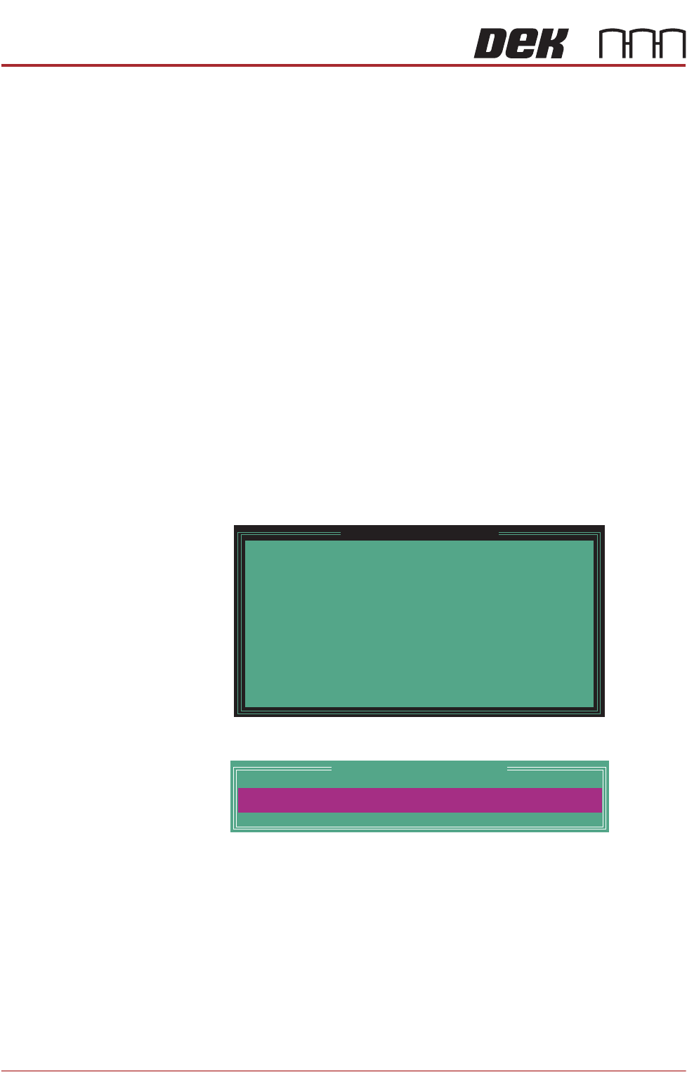
The rising table moves to the default setting and the following window is
displayed:
10. Select Confirm to open the Table Print Height Calibration window:
11. Check the gap between the top of the board clamps and the screen. The
correct print height is when the top of the transport rails is just touching the
screen.
12. Use the Incr. or Decr. button to adjust the displayed dimension.
13. Select Move.
14. Repeat Steps 11 to 13 until the top of the board clamps are in contact with
the screen, without force.
15. When the correct height has been achieved, select Set Height.
Please confirm the following:
There is a screen loaded.
There is NO board loaded.
The aim of this calibration is to set the elevation of
the rising table to the point where the closed board
clamps are just in contact with the stencil.
While foil-less clamps or snuggers are being used,
ensure they have been adjusted to bring their top
surface level with the top surface of the board.
Upon completion of this calibration, the Squeegee
Reference Height should also be calibrated.
Set Reference Print Height
PRINT HEIGHT
Table Print Height Calibration
127.00
mm