192277 - Micron Technical Reference Volume 3 - 第142页
RISING TABLE MODULE - STYLE 1 TEST CYCLES 27.12 Technical Reference Manual Chapter Issue 9, Aug 14 TEST CYCLES For information on the T est Cycle functi on ref er to the Screen Alignment Module chapter of this manual.

RISING TABLE MODULE - STYLE 1
CALIBRATIONS
Chapter Issue 9, Aug 14 Technical Reference Manual 27.11
The following window is displayed:
16. Select Confirm to save the new print height.
17. Select Cancel to close the Set Reference Vision Height window.
18. Select Exit.
19. Select Exit.
20. Select Back.
21. Carry out the Squeegee Reference Height calibration, Squeegee chapter
refers.
Please confirm the following:
The board clamps are not lifting the stencil.
When the part of the stencil that is over the board
clamps is pressed, there is no perceptible movement.
To adjust the elevation of the board clamps, press
Cancel. Use Incr. And Decr. to alter the value of print
height. Use Move to apply the current value of print
height.
Set Reference Vision Height

RISING TABLE MODULE - STYLE 1
TEST CYCLES
27.12 Technical Reference Manual Chapter Issue 9, Aug 14
TEST CYCLES
For information on the Test Cycle function refer to the Screen Alignment Module
chapter of this manual.
RISING TABLE MODULE - STYLE 2
OVERVIEW
Chapter Issue 3, Feb 18 Technical Reference Manual 28.1
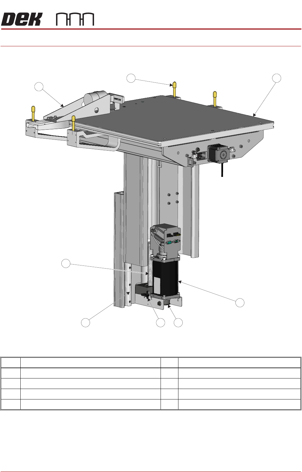
CHAPTER 28 RISING TABLE MODULE - STYLE 2
OVERVIEW
NOTE
For details on the Remote Board Stop and sensors refer to the Board Stop
Chapter.
Item Description Item Description
1 Manual Tooling Plate 5 Linear Bearing Guide (in 2 positions)
2 Rising Table Motor with Integral Electromagnetic Brake 6 Rising Table Leadscrew
3 Rising Table drive belt 7 Remote Board Stop (Optional) See Note.
4 Home Sensor 8 Rail to Table Height Adjuster (in 4 positions)
View on Rear of Rising TableLeft
5
2
7
1
4 3
6
8