192277 - Micron Technical Reference Volume 3 - 第156页
BOARD SUPPORT TO OLING MODULE VACUUM BOX TOOLING 29.4 Technical Reference Manual Chapter Issue 7, Jan 15 Figure 29-4 V acuum Box T ooling Rapid T ransit Conveyor Nominal Board Length -4mm 2mm ( overhang of board, each en…
BOARD SUPPORT TOOLING MODULE
VACUUM BOX TOOLING
Chapter Issue 7, Jan 15 Technical Reference Manual 29.3
VACUUM BOX TOOLING
The vacuum box is manufactured to the same height as the magnetic pins, ie
81mm, irrespective of the thickness of the board being printed. The vacuum
boxes can be constructed without top or bottom plates to allow for additional pin
support of the board. Provision for machining of top plates to accommodate
underside components is available. The box is located on the table by means
of dowels which locate in the two holes on the manual tooling plate.
The minimum length of the vacuum box is 90mm which is dictated by the
locating dowels. Where the board length is less than the vacuum box length,
top plates either side of the board must be used to achieve vacuum.
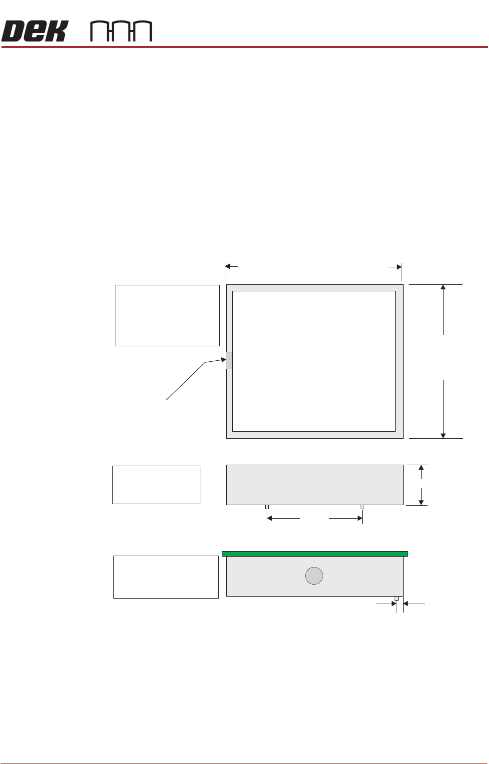
The following graphic details the dimensional information on the vacuum box
tooling for use on the rising table:
Figure 29-3 Vacuum Box Tooling
NOTE
For RTC or Dual Lane machines the vacuum box dimensions, as shown above,
must not be used. Contact ASM Customer support for details of the correct
dimensions to be used.
Plan View of Vacuum Box
Nominal Board
Width -12mm
6mm( overhang
of board, each end)
36mm Vacuum Hole
Insert Magnetic Pins as Required
Front View of Vacuum Box
81mm
80mm
+0.00mm
-0.05mm
NOTE
2 Front Dowel Pins
( diameter)3mm
NOTE
For Dual Lane machines
Right to Left and Left to
Right a 12mm elbow and
a machined adaptor ring
is fitted
Left Hand Side View of Vacuum Box
2.5mm
NOTE
View showing board
positioned on Vacuum
Box
Nominal Board Length -4mm
2mm( overhang of board, each end)
90mm 508mmMinimum Maximum
BOARD SUPPORT TOOLING MODULE
VACUUM BOX TOOLING
29.4 Technical Reference Manual Chapter Issue 7, Jan 15
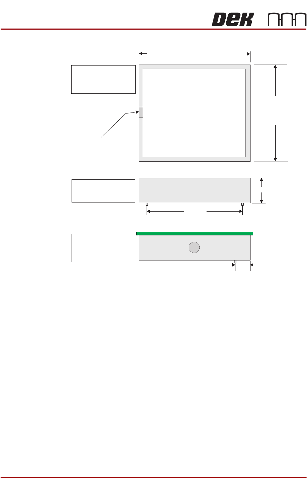
Figure 29-4 Vacuum Box Tooling Rapid Transit Conveyor
Nominal Board Length -4mm
2mm( overhang of board, each end)
290mm 375mmMinimum Maximum
Plan View of Vacuum Box
Nominal Board
Width -13.5mm
6mm(overhang rear
)and front7.5mm
36mm Vacuum Hole
Insert Magnetic Pins as Required
Front View of Vacuum Box
81mm
280mm
+0.00mm
-0.05mm
NOTE
2 Front Dowel Pins
( diameter)4mm
Left Hand Side View of Vacuum Box
29.5mm
NOTE
View showing board
positioned on Vacuum
Box
NOTE
A 12mm elbow and
a machined adaptor ring
is fitted
BOARD SUPPORT TOOLING MODULE
DEDICATED TOOLING SYSTEM
Chapter Issue 7, Jan 15 Technical Reference Manual 29.5
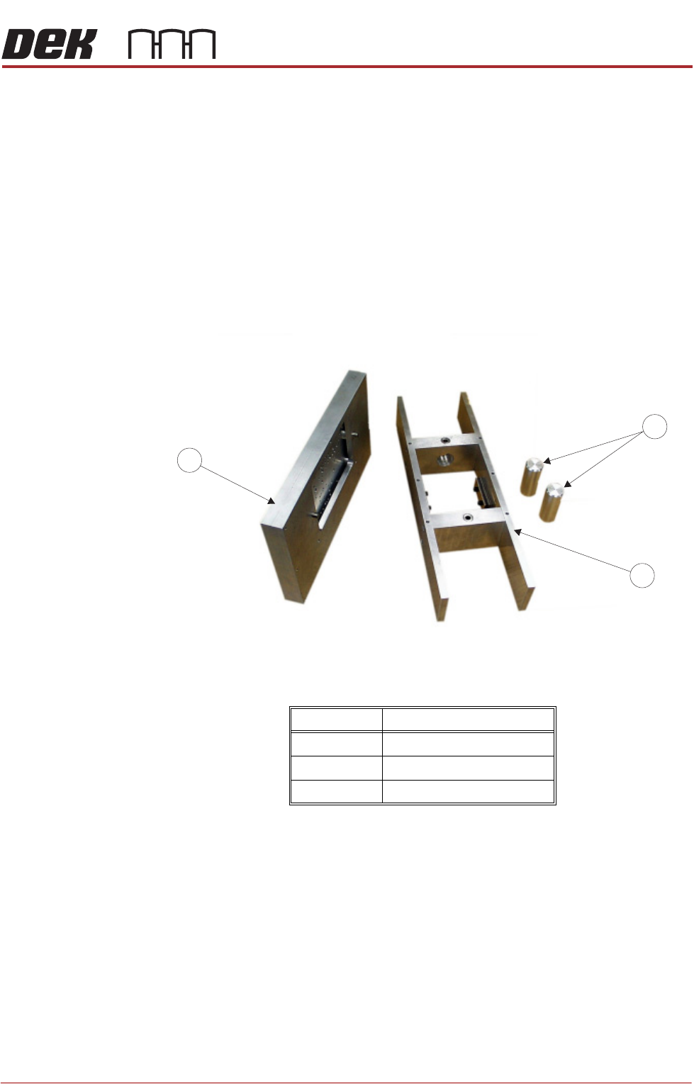
DEDICATED TOOLING SYSTEM
The dedicated tooling system is a 3-piece construction comprising a plate
assembly which locates on a tooling tower and magnetic support pins that
provide support under the plate assembly when accommodating wide boards.
The system is manufactured to provide board support at the standard tooling
height of 81mm. The plate assembly can be specifically machined to accom-
modate underside components on customers products.
The tooling tower has dowel pin registration and is held in position on the
manual tooling plate by two magnetic clamps located in the vacuum chamber
of the tooling tower. Additional board support can be utilized with the optional
vacuum facility.
Figure 29-5 Dedicated Tooling System
Item Description
1 Plate Assembly
2 Tooling Tower
3 Magnetic Tooling Pins
1
3
2