192277 - Micron Technical Reference Volume 3 - 第158页
BOARD SUPPORT TO OLING MODULE PROFLOW STENCIL SUPPORT 29.6 Technical Reference Manual Chapter Issue 7, Jan 15 PROFLOW STENCIL SUPPORT The ProFlow Stencil Support unit provides stencil support when printing with ProFlow a…
BOARD SUPPORT TOOLING MODULE
DEDICATED TOOLING SYSTEM
Chapter Issue 7, Jan 15 Technical Reference Manual 29.5
DEDICATED TOOLING SYSTEM
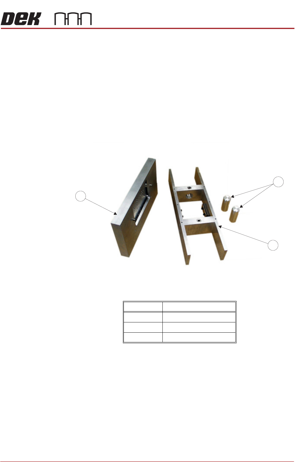
The dedicated tooling system is a 3-piece construction comprising a plate
assembly which locates on a tooling tower and magnetic support pins that
provide support under the plate assembly when accommodating wide boards.
The system is manufactured to provide board support at the standard tooling
height of 81mm. The plate assembly can be specifically machined to accom-
modate underside components on customers products.
The tooling tower has dowel pin registration and is held in position on the
manual tooling plate by two magnetic clamps located in the vacuum chamber
of the tooling tower. Additional board support can be utilized with the optional
vacuum facility.
Figure 29-5 Dedicated Tooling System
Item Description
1 Plate Assembly
2 Tooling Tower
3 Magnetic Tooling Pins
1
3
2
BOARD SUPPORT TOOLING MODULE
PROFLOW STENCIL SUPPORT
29.6 Technical Reference Manual Chapter Issue 7, Jan 15
PROFLOW STENCIL SUPPORT
The ProFlow Stencil Support unit provides stencil support when printing with
ProFlow and helps to avoid smearing paste onto the top of the stencil.
These are used mainly when printing boards that are narrower than the ProFlow
transfer head (300mm minimum).
The ProFlow Stencil Support is compatible with all tooling options. The stand-
ard height (when the adjustable tooling top is in the closed position) is 81mm.
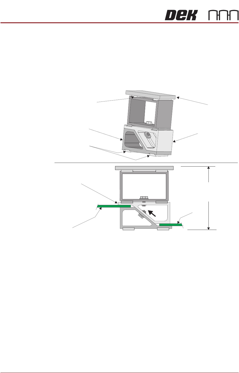
Figure 29-6 ProFlow Stencil Support
Changeable Gauge
Plate
The Changeable Gauge Plate, standard thickness 3/16" (4.77mm), may be
changed in order to support larger stencil areas. These are easily removed and
held in position by fixed magnetic supports.
Tooling Bottom The Tooling Bottom is the fixed base for the stencil support with magnetic feet
attached for easy position on the tooling table.
Adjustable Tooling
Top
The Adjustable Tooling Top can be moved by releasing the 7mm hexagonal nut
securing it to the tooling bottom. The unit can be slid upwards, raising the height
of the support unit, to the desired height.
Changeable
Gauge Plate
Tooling Bottom
Magnetic Feet
Magnetic Support
(2 positions)
Adjustable Tooling
Top
Board
Adjustable
Tooling Top
Board
Stencil Support
Height (81mm +
PCB Thickness)
BOARD SUPPORT TOOLING MODULE
GRID-LOK TOOLING
Chapter Issue 7, Jan 15 Technical Reference Manual 29.7
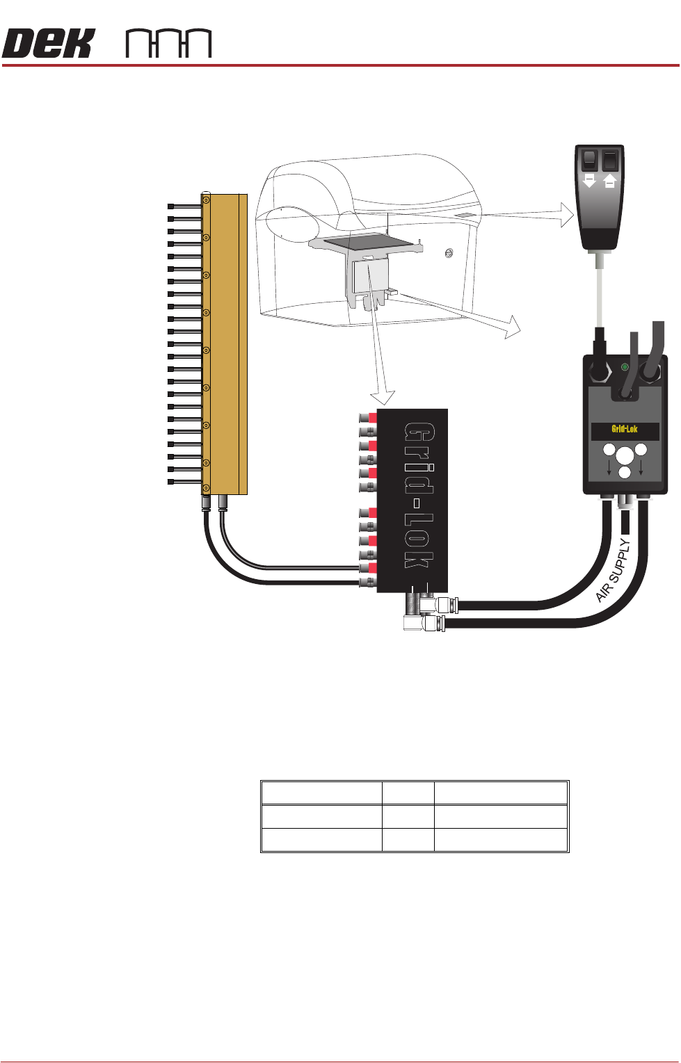
GRID-LOK TOOLING
Overview
Grid-Lok tooling is a fully automated tooling facility that conforms to any given
board profile, fully supporting the underside of a populated board and the
stencil.
The Grid-Lok tooling module is only available with a double row of tooling pins
with a 12mm pitch.
The tooling modules are available in two sizes:
The Grid-Lok tooling module is held magnetically to the manual tooling plate.
Size Pins Modules Supplied
12 inch (305mm) 46 3
18 inch (457mm) 72 5
Grid-Lok
Control Unit
Operator
Interface
AUTO
SEMI
AUTO
SET
RESET
Grid-Lok
CS
24
VDC
12
P
AIR
IN
24V SUPPLY
TRIGGER
Tooling Module
(Maximum of 6)
Manifold
1
2