192277 - Micron Technical Reference Volume 3 - 第163页
BOARD SUPPORT TO OLING MODULE GRID-LOK TOOLING Chapter Issue 7, Jan 15 Technical Reference Manual 29.11 Adjustments and Settings W ARNING BOARD CLAMPS. EXTREME CA RE MUST BE EXERCIS ED WHEN WORKING IN THE TOOLING AREA OF…
BOARD SUPPORT TOOLING MODULE
GRID-LOK TOOLING
29.10 Technical Reference Manual Chapter Issue 7, Jan 15
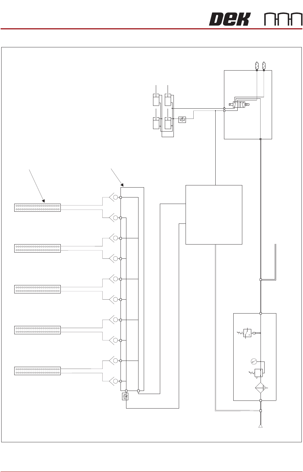
Pneumatic Schematic
Tooling Modules
Grid-Lok Manifold
Grid-Lok Control Unit
P
Pressure
Sense
Filter/Reg Assy
Mains Air to Machine
A
B
5/2
Pos 7
Board Clamps
Pneumatic Manifold (part of)
Mains
Air In
At 4.5 Bar
Minimum
BOARD SUPPORT TOOLING MODULE
GRID-LOK TOOLING
Chapter Issue 7, Jan 15 Technical Reference Manual 29.11
Adjustments and Settings
WARNING
BOARD CLAMPS. EXTREME CARE MUST BE EXERCISED WHEN WORKING IN
THE TOOLING AREA OF THE MACHINE TO AVOID INJURY. THE FOILS ON THE
FRONT AND REAR BOARD CLAMPS ARE VERY SHARP.
Grid-Lok Control
Unit
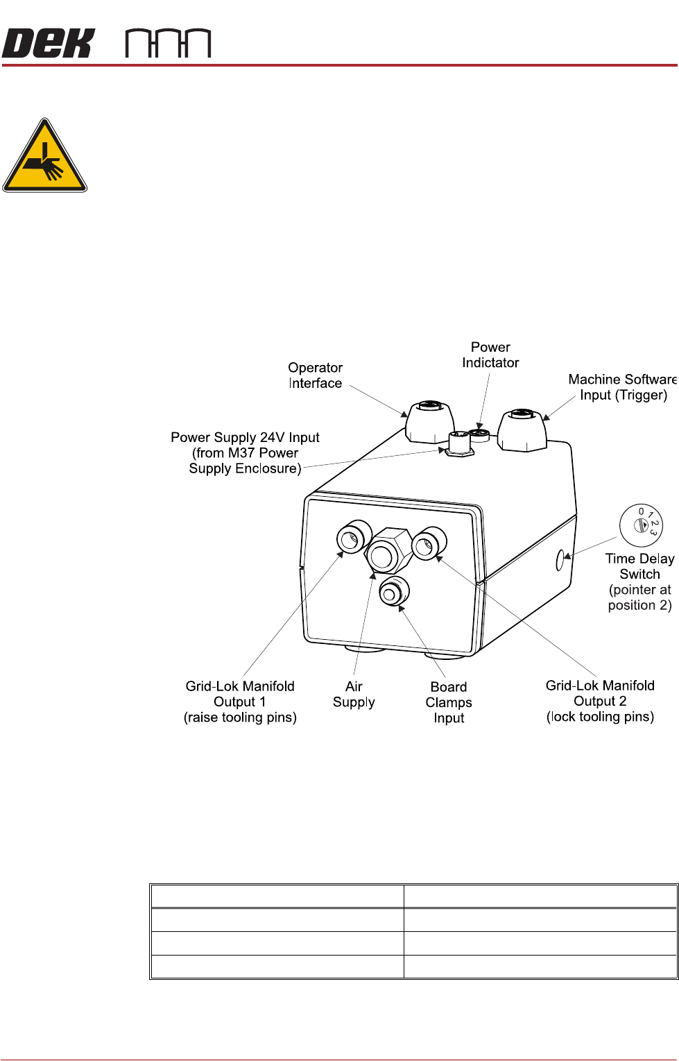
The Grid-Lok control unit is located behind the rear panel and is mounted on
the pneumatic manifold plate.
The control unit incorporates all the pneumatic and electrical control systems
required to raise and lower the Grid-Lok tooling pins.
An access hole on the right side panel is used to gain access to the function
switch.
The controller switch sets the delay of the tooling pins being raised after the
board leaves vision height, in automatic mode. Each setting determines the
trigger delay.
The following table shows the controller switch settings for the trigger delay:
NOTE
The controller switch must be set to 0 when using 81mm pins.
Controller Switch setting Trigger delay
Zero (0) 0.0 seconds
One (1) 300 milliseconds
Two (2) 600 milliseconds

BOARD SUPPORT TOOLING MODULE
GRID-LOK TOOLING
29.12 Technical Reference Manual Chapter Issue 7, Jan 15
Air Control
Regulator
The air control regulator is fitted to the top input of the Grid-Lok manifold and is
used to adjust the air flow to the raise pins input of the tooling modules.
Figure 29-7 Air Control Regulator
To adjust the air control regulator, use the following procedure:
1. Ensure the operator interface is switched to Manual.
2. Release the locking nut on the air control regulator.
3. Adjust the air control regulator fully clockwise cutting off the air supply to the
tooling modules.
4. Adjust the air control regulator one turn anti-clockwise.
5. Press the Set button on the operator interface.
6. If all the pins on the tooling modules do not raise fully, press the Reset button
on the operator interface and repeat Steps 4 and 5.
7. If all the pins on the tooling modules raise fully, turn the air control regulator
a further half turn anti-clockwise and secure the locking nut.
8. Press the Reset button on the operator interface.
NOTE
Adjustment of the air control regulator must be performed when changing the
amount of tooling modules used.
Locking Nut
Air Control Regulator