192277 - Micron Technical Reference Volume 3 - 第165页
BOARD SUPPORT TO OLING MODULE REPLACEMENT PROCEDURES Chapter Issue 7, Jan 15 Technical Reference Manual 29.13 REPLACEMENT PROCE DURES Fitting Grid-Lok T ooling W ARNING BOARD CLAMPS. EXTREME CA RE MUST BE EXERCIS ED WHEN…
BOARD SUPPORT TOOLING MODULE
GRID-LOK TOOLING
29.12 Technical Reference Manual Chapter Issue 7, Jan 15
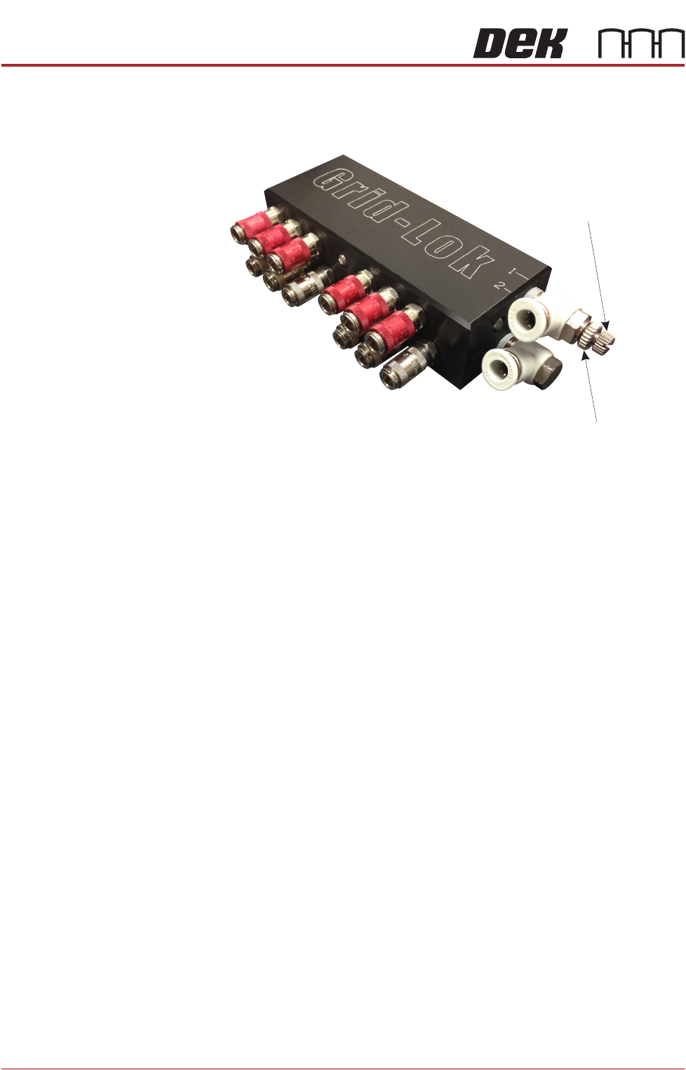
Air Control
Regulator
The air control regulator is fitted to the top input of the Grid-Lok manifold and is
used to adjust the air flow to the raise pins input of the tooling modules.
Figure 29-7 Air Control Regulator
To adjust the air control regulator, use the following procedure:
1. Ensure the operator interface is switched to Manual.
2. Release the locking nut on the air control regulator.
3. Adjust the air control regulator fully clockwise cutting off the air supply to the
tooling modules.
4. Adjust the air control regulator one turn anti-clockwise.
5. Press the Set button on the operator interface.
6. If all the pins on the tooling modules do not raise fully, press the Reset button
on the operator interface and repeat Steps 4 and 5.
7. If all the pins on the tooling modules raise fully, turn the air control regulator
a further half turn anti-clockwise and secure the locking nut.
8. Press the Reset button on the operator interface.
NOTE
Adjustment of the air control regulator must be performed when changing the
amount of tooling modules used.
Locking Nut
Air Control Regulator
BOARD SUPPORT TOOLING MODULE
REPLACEMENT PROCEDURES
Chapter Issue 7, Jan 15 Technical Reference Manual 29.13
REPLACEMENT PROCEDURES
Fitting Grid-Lok Tooling
WARNING
BOARD CLAMPS. EXTREME CARE MUST BE EXERCISED WHEN WORKING IN
THE TOOLING AREA OF THE MACHINE TO AVOID INJURY. THE FOILS ON THE
FRONT AND REAR BOARD CLAMPS ARE VERY SHARP.
WARNING
COMPRESSED AIR. COMPRESSED AIR SHOULD NEVER IMPINGE UPON THE
BODY. PORTS, PIPES, ETC MUST NEVER BE BLOCKED BY HAND. BEFORE
CONNECTING OR DISCONNECTING ANY PNEUMATIC COMPONENTS, ENSURE
THE COMPRESSED AIR SUPPLY HAS BEEN DISSIPATED AND DISCONNECTED
FROM THE MACHINE.
1. Select Open Cover Commands.
2. Select Carriage To Rear.
3. Select Shut Down and switch the mains isolator to OFF.
4. Open the front printhead cover.
5. Remove the stencil from the machine.
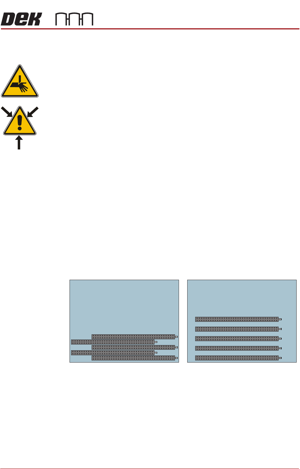
6. The tooling modules can be configured to suit the product to be printed. The
tooling modules can be staggered in the X axis and/or spread evenly in the
Y axis to fully support the product to be printed (see figure below for
examples).
NOTE
Tooling modules must never be placed underneath the front or rear rails.
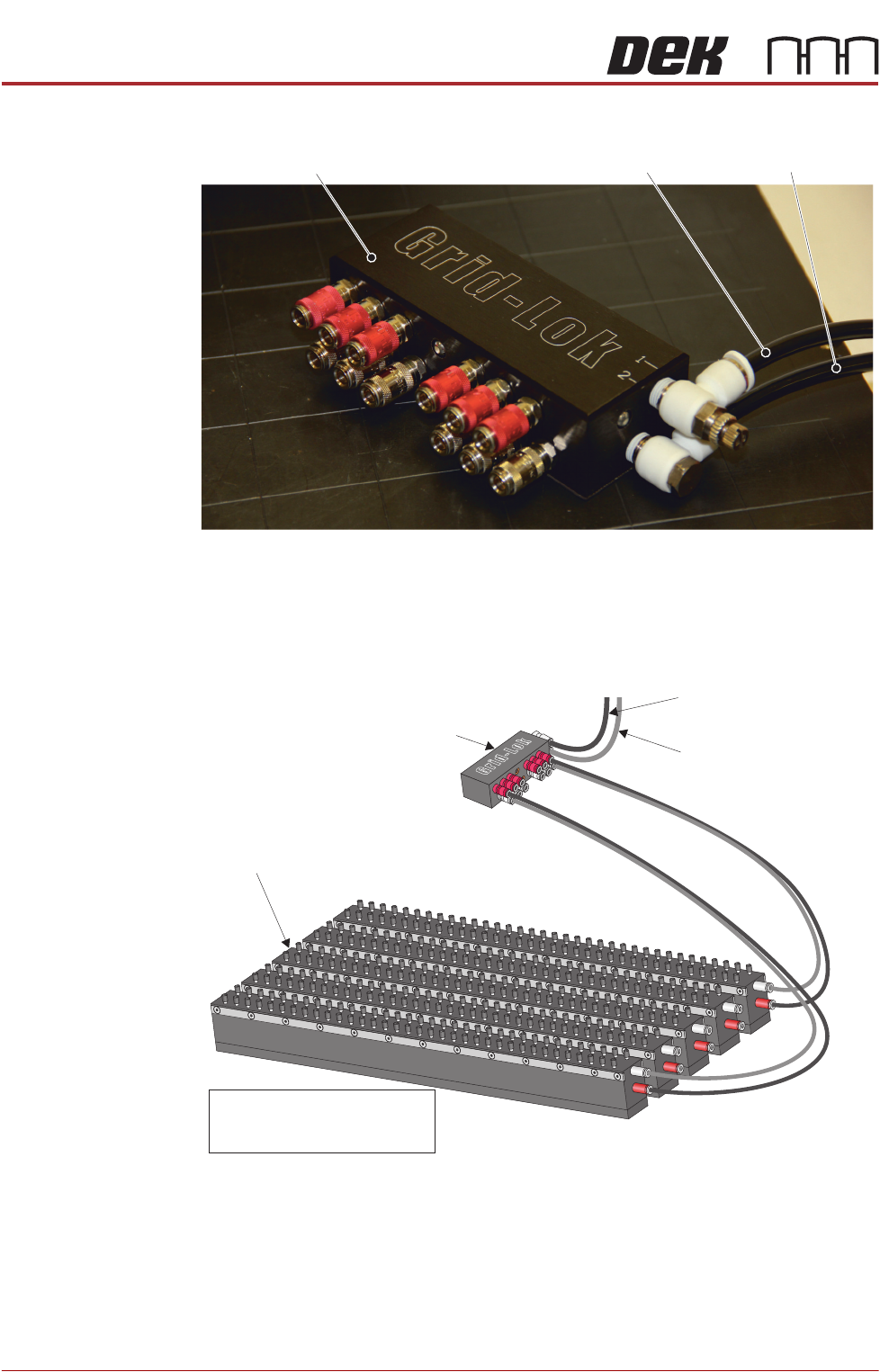
7. Place the manifold on the rear of the tooling plate.
8. Connect the 6mm diameter pneumatic pipe marked 1 to the top 6mm
connector of the Grid-Lok manifold.
9. Connect the 6mm diameter pneumatic pipe marked 2 to the bottom 6mm
Plan View on Manual Tooling Plate
5
4
3
2
1
5
4
3
2
1
BOARD SUPPORT TOOLING MODULE
REPLACEMENT PROCEDURES
29.14 Technical Reference Manual Chapter Issue 7, Jan 15
connector of the Grid-Lok manifold.
10. Connect 4mm diameter pneumatic pipes from the manifold to all the tooling
modules ensuring that the outputs marked red on the manifold connect to
the inputs marked red of the tooling modules.
View from Right Hand Side of the Machine
Grid-Lok Manifold
Pneumatic Pipe 1 Pneumatic Pipe 2
Grid-Lok Manifold
To Connector 1 of the
Grid-Lok Control Unit
To Connector 2 of the
Grid-Lok Control Unit
Tooling Modules
NOTE
Only tooling modules 1 and 5
are connected for clarity