192277 - Micron Technical Reference Volume 3 - 第171页
PASTE ROLL HEIGHT MONITOR MODULE OVERVIEW Chapter Issue 3, Aug 14 Technical Reference Manual 30.3 MODULE OVERVIEW Purpose The optional Roll Height Monitor detects the height of the roll of the print medium, if insuf fici…

PASTE ROLL HEIGHT MONITOR
SAFETY INFORMATION
30.2 Technical Reference Manual Chapter Issue 3, Aug 14
In addition, the following general safety labels are presented throughout this
chapter.
CAUTION
RADIATION. RISK OF INJURY TO THE EYES DUE TO LASER LIGHT BEING
PRESENT IN THE VICINITY OF THE LABEL. DO NOT LOOK AT THE LIGHT
SOURCE OR REFLECTIONS FROM A SURFACE.
CAUTION
EQUIPMENT SERVICING. THE LASER DOES NOT CONTAIN USER
SERVICEABLE PARTS. OPENING THE UNIT COULD CAUSE MIS-ALIGNMENT OF
THE LASER, THIS MAY MAKE THE EQUIPMENT DANGEROUS TO OPERATE.
CAUTION
LASER CONTROLS AND ADJUSTMENTS. USE OF CONTROLS OR
ADJUSTMENTS OR PERFORMANCE OF PROCEDURES OTHER THAN THOSE
SPECIFIED HEREIN MAY RESULT IN HAZARDOUS RADIATION EXPOSURE.

PASTE ROLL HEIGHT MONITOR
MODULE OVERVIEW
Chapter Issue 3, Aug 14 Technical Reference Manual 30.3
MODULE OVERVIEW
Purpose The optional Roll Height Monitor detects the height of the roll of the print
medium, if insufficient height of the print medium roll is sensed an automatic
paste dispense operation is initialized.
Elements The Roll Height Monitor consists of the following:
• Roll Height Monitor Assembly
• Voltage Regulator
Operation The Roll Height Monitor assembly is fitted to the machine replacing the front
squeegee ‘I’ bar mount. The front squeegee is fitted to the assembly in the same
way as it fits the squeegee ‘I’ bar mount. The laser light source is fitted to the
left hand leg of the assembly and the light receiver is fitted to the right hand leg.
The light source and receiver are positioned such that the line of sight between
them is in front and between 10mm - 16mm above the tip of the squeegee. As
the machine performs a print stroke to the rear, the height of the print medium
roll in front of the squeegee is monitored between 50% and 90% of the print
stroke. If the receiver acquires light from the light source a paste dispense
operation is initialized and an entry is written to the event log file. If the entry in
the event log equals or exceeds three, the tricoloured beacon displays red and
an error message ‘Insufficient Print Medium Has Been Dispensed.’ The
option to replenish the paste dispenser is given.
PASTE ROLL HEIGHT MONITOR
ELECTRICAL SCHEMATIC
30.4 Technical Reference Manual Chapter Issue 3, Aug 14
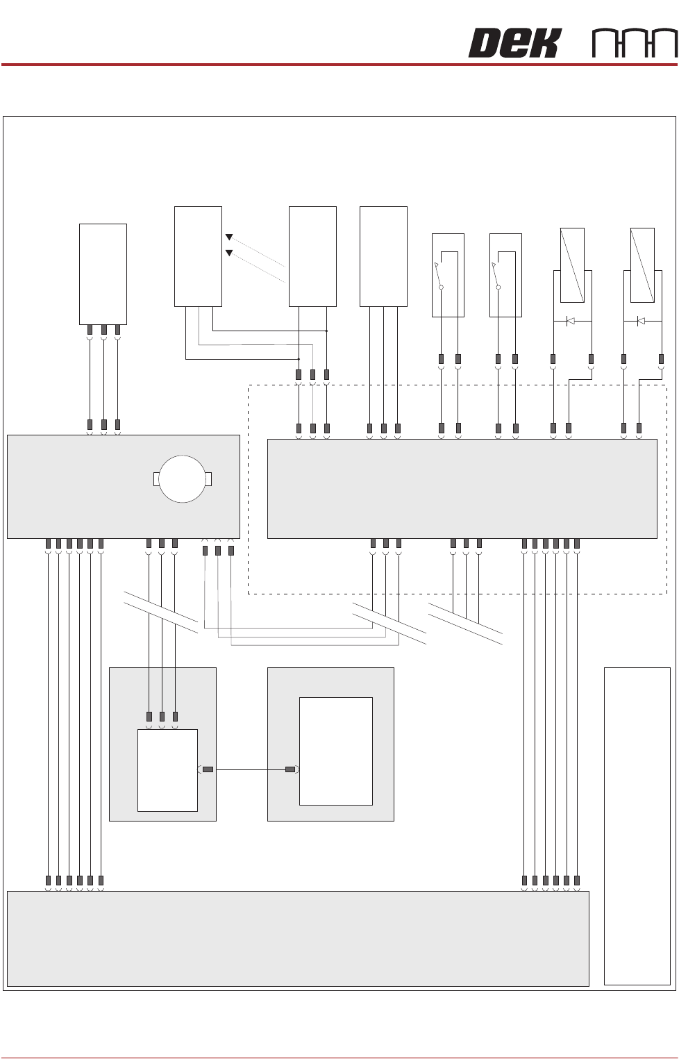
ELECTRICAL SCHEMATIC
Paste Level
Sensor
9SE15
Roll Height
Sensor
9SE24
Roll Height
Laser
+12V
Signal
0V
+12V SW
Signal
0V
+12V SW
0V
N3PL11
N3PL4
DIG IN 9
DIG IN 2
Paste Cartridge
Horizontal Sensor
9SE13
N3PL10
DIG IN 8
Paste Pressure
Solenoid
9SOL26
N3PL8
DIG OUT 4
Paste Cartridge
Tilt Actuator
9SOL27
N3PL8
DIG OUT 5
Paste Cartridge
Vertical Sensor
9SE14
N3PL10
DIG IN 7
Print Carriage
Print Carriage
I/O Node 3
Paste Dispense
Stepper Node 10
N3SK2
N3SK3
N10PL4
PC
Single Board
Computer (SBC)
or
Motherboard
USB
CAN
Out
CAN
Out
CAN
In
M36PL35
NextMove ES
(I/O Node 1)
M36 Machine Control
N3SK3
CAN Bus
CAN
In
NOTE
The breaks in the CAN Bus chain reflect that additional
I/O Nodes may be fitted, refer to Machine Control
chapter for the complete CAN Bus chain.
Paste Dispenser
Home Sensor
9SE12
+24V
Signal
0V
N10PL1
M
I/O3
N3PL44
N3PL44
9PL27
9PL26
9SE12
M37 PSU
Enclosure
+24V US
0V Return
+24V SW
0V Return
+12V
0V Return
N10SK2
M37PL08
+24V US
0V Return
+24V SW
0V Return
+12V
0V Return
N3SK1
M37PL05
9PL60