192277 - Micron Technical Reference Volume 3 - 第182页
AIR IONI ZER MODULE OVERVIEW 31.2 Technical Reference Manual Chapter Issue 5, Aug 14 The air ionizer reduces the a mount of stat ic electricity to +100V , making it safe for most static sensitive components which ent er …
AIR IONIZER MODULE
OVERVIEW
Chapter Issue 5, Aug 14 Technical Reference Manual 31.1
CHAPTER 31 AIR IONIZER MODULE
OVERVIEW
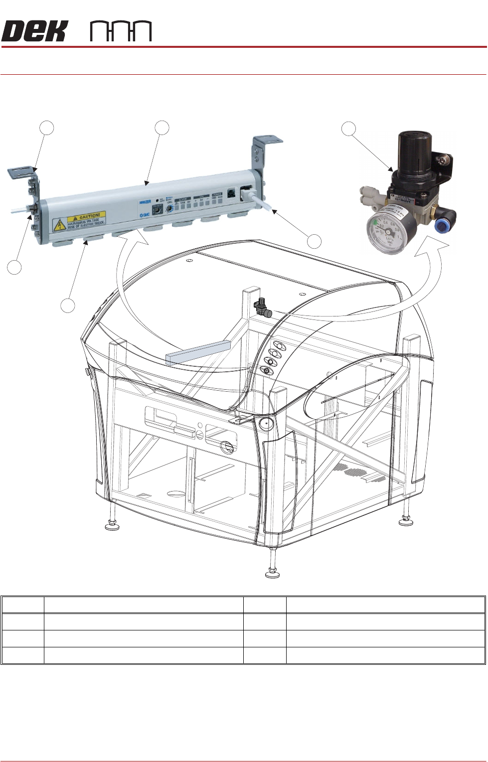
Item Description Item Description
1 Air Inlet 4 Air Regulator
2 Air Ionizer Bracket (in 2 positions) 5 +24VSW Power In
3 Air Ionizer 6 Air Ionizer Electrodes
1
5
6
2
3
4

AIR IONIZER MODULE
OVERVIEW
31.2 Technical Reference Manual Chapter Issue 5, Aug 14
The air ionizer reduces the amount of static electricity to +100V, making it safe
for most static sensitive components which enter the machine.
Air is supplied to the input of the ionizing unit. An array of electrodes, mounted
on the base of the unit, ionizes the air supply. The electrodes consist of a pair
of corona discharge needles which receive a positive and negative dc waveform
at 7kV, 20Hz: producing an ionizing potential of+100V.
The electrodes are housed in a cartridge, which makes them easy to fit and
remove from their housing. Three types are available:
• Tungsten: ion balance +30V
• Silicon: ion balance +30V (used in environments sensitive to metal con-
tamination)
• Stainless Steel: ion balance +100V
Currently, ASM supply the stainless steel electrode units.
The air supply, set to 2 bar, is routed over the electrodes, ensuring a wide
dispersal of ionized air; this functionality increases the speed of static reduction.
Modes of
Operation
There are three modes of operation:
• Sensing DC Mode
• Pulse DC Mode
• DC Mode
Pulse DC Mode Currently, ASM utilise the Pulse DC Mode. The ionizer alternately emits positive
and negative ions (pulsed dc) to dissipate any spatial static charge, which may
be present in the working area.
If the ion balance voltage exceeds +100V, this may be due to needle contami-
nation; the ionizer outputs a maintenance signal. This action causes a needle
check indicator to initially pulse on and off, signalling that there may be needle
contamination. After a period of time, the indicator stays on signalling that
maintenance is required. Usually this consists of cleaning the electrode pairs.
Power Supply The air ionizer derives its power from the 24V switched supply (M37) and is
disabled when the printhead cover is open or the E Stop is pressed.
NOTE
When the air ionizer is electrically disabled, air pressure continues to flow
through the electrodes.
AIR IONIZER MODULE
ELECTRICAL & PNEUMATIC SCHEMATICS
Chapter Issue 5, Aug 14 Technical Reference Manual 31.3
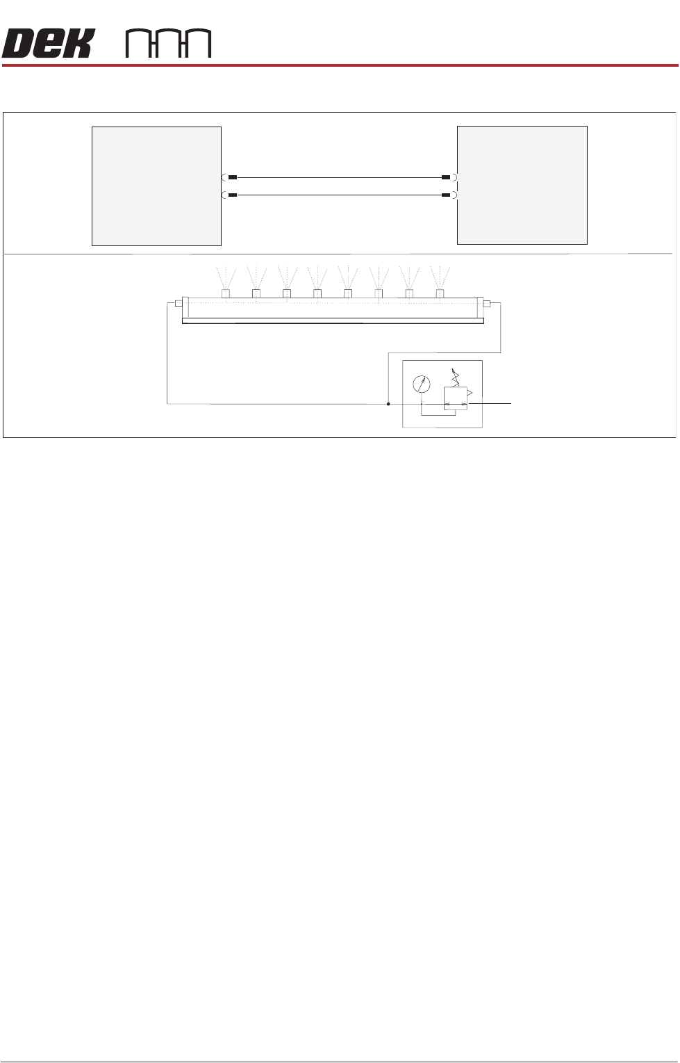
ELECTRICAL & PNEUMATIC SCHEMATICS
M37 Power
Supply Enclosure
Electrical
Pneumatic
Air Ionizer
M37PL11
24V SW
OV
8PL100
Air Ionizer
Out
In