192277 - Micron Technical Reference Volume 3 - 第189页
BARCODE READER AND VERIFICATION AND TRACEABILITY OVERVIEW Chapter Issue 10, Feb 17 Technical Reference Manual 32.1 CHAPTER 32 BARCOD E READER AND VERIFICA TION AND TRACEABILITY OVER VI EW There are two types of b arcode …
AIR IONIZER MODULE
REPLACEMENT PROCEDURES
31.8 Technical Reference Manual Chapter Issue 5, Aug 14
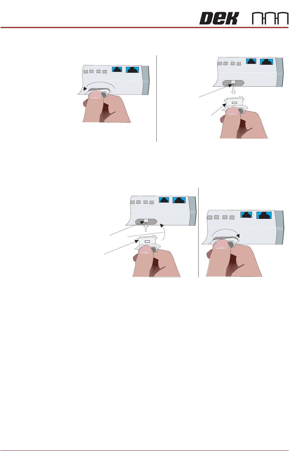
3. To remove the electrode cartridge, twist it counter clockwise (1) and pull it
out of the ionizer assembly (2).
4. Discard the electrode cartridge.
5. With the new electrode cartridge, slightly angled up toward the front face of
the assembly (1), slide it into the cartridge socket, ensuring that the unit
seats onto the alignment pin.
6. Twist the electrode cartridge clockwise to lock it in position (2).
7. Repeat Steps 3 to 6 for all the remaining electrode cartridges.
8. Refit the left hand side safety cover.
12
Twist to Unlock
Electrode Cartridge
Alignment Pin
Withdraw Electrode
Cartridge
Front Face
Electrode Cartridge
1
2
Alignment Pin
Angled Alignment
Front Face
Twist to Lock
BARCODE READER AND VERIFICATION AND TRACEABILITY
OVERVIEW
Chapter Issue 10, Feb 17 Technical Reference Manual 32.1
CHAPTER 32 BARCODE READER AND VERIFICATION AND TRACEABILITY
OVERVIEW
There are two types of barcode readers that may be fitted to the machine:
• Remote Barcode Reader
• Handheld Barcode Reader
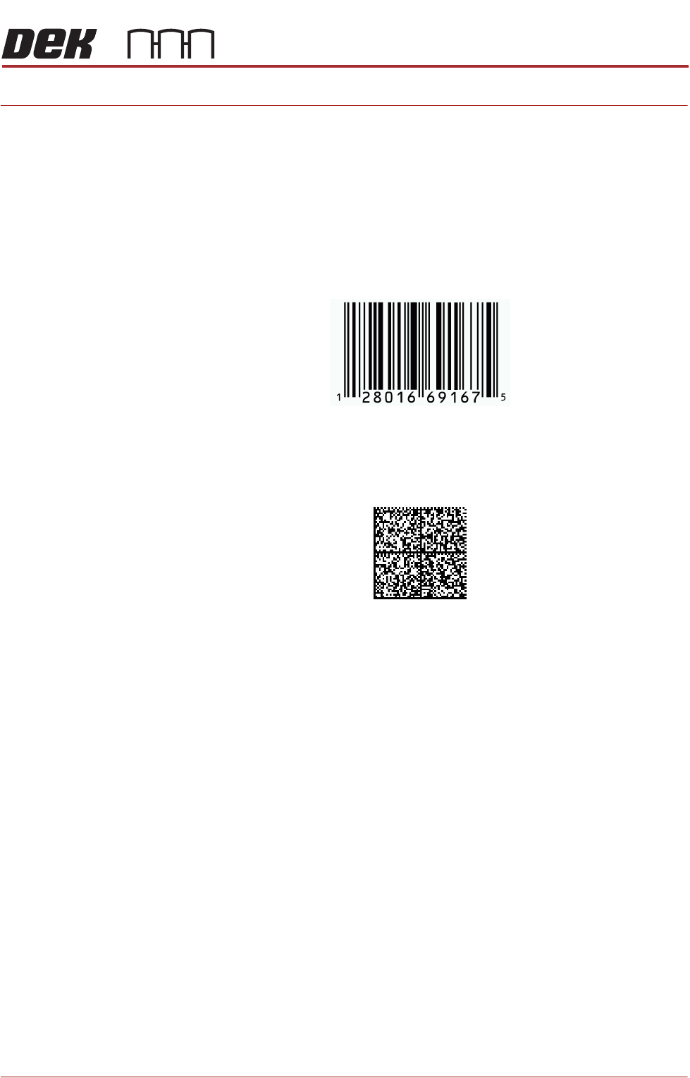
1D or one dimensional barcodes are the most common barcodes consisting of
a single row of different width bars.
2D or two dimensional barcodes consist of square modules constructed in a
matrix that may be square or rectangular.
NOTE
There are many different formats of barcodes: Data matrix, Aztec, QR, PDF
417. In the graphics above, these are single examples to demonstrate the
difference between 1D and 2D barcodes.
Example of a 1D Barcode
Example of a 2D Barcode
BARCODE READER AND VERIFICATION AND TRACEABILITY
OVERVIEW
32.2 Technical Reference Manual Chapter Issue 10, Feb 17
CAUTION
LASER CONTROLS AND ADJUSTMENTS. USE OF CONTROLS OR
ADJUSTMENTS OR PERFORMANCE OF PROCEDURES OTHER THAN THOSE
SPECIFIED HEREIN MAY RESULT IN HAZARDOUS RADIATION EXPOSURE.
CAUTION
RADIATION. RISK OF INJURY TO THE EYES DUE TO LASER LIGHT BEING
PRESENT IN THE VICINITY OF THE LABEL. DO NOT LOOK AT THE LIGHT
SOURCE OR REFLECTIONS FROM A SURFACE.
CAUTION
EQUIPMENT SERVICING. THE LASER DOES NOT CONTAIN USER
SERVICEABLE PARTS. OPENING THE UNIT COULD CAUSE MIS-ALIGNMENT OF
THE LASER, THIS MAY MAKE THE EQUIPMENT DANGEROUS TO OPERATE.
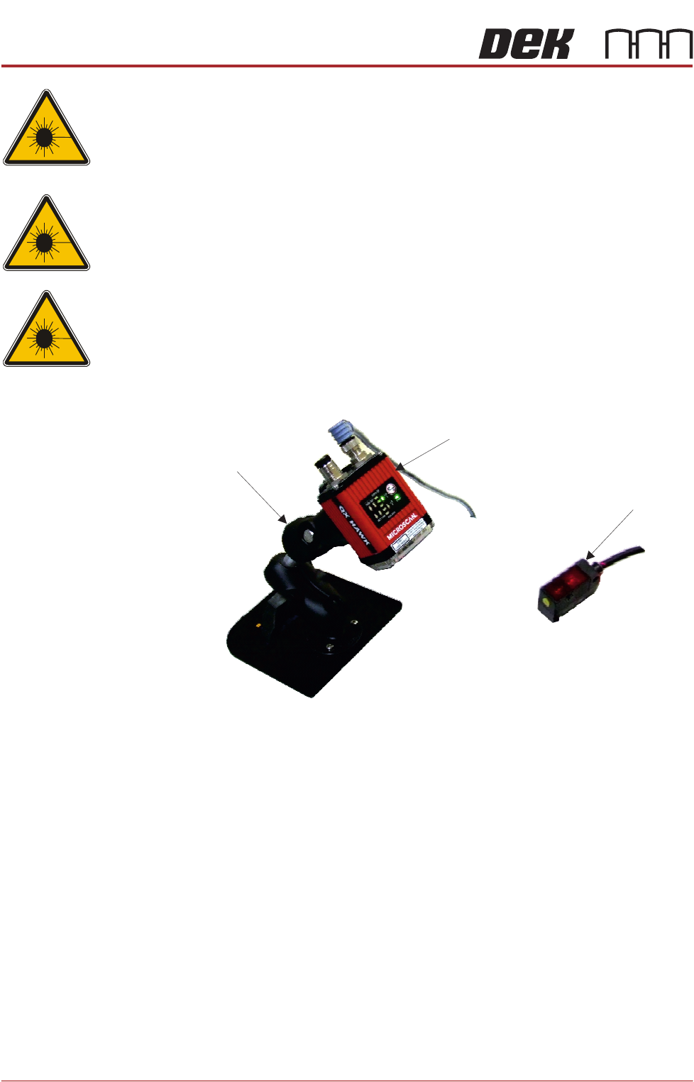
Remote Barcode
Reader
The remote barcode reader is located on the input conveyor to the printer and
reads the barcode of the incoming product. It also provides information to the
Verification and Traceability software option.
The system comprises a mounting stand, the reader, a suitable barcode on the
product (not shown), an in-line trigger sensor and a set of configuration cards.
The stand is mounted onto a customer’s input conveyor. The configuration
cards are used to aid the barcode reader set up and calibration. The sensor is
attached forward of the reader using a Velcro fastener.
During the board/product transfer cycle, with the remote barcode option ena-
bled, the trigger sensor detects the board on the conveyor; it triggers the remote
barcode reader to read the barcode, before the board is passed into the printer.
Mounting Stand
Barcode Reader
Trigger Sensor