192277 - Micron Technical Reference Volume 3 - 第20页
RAPID TRANSIT CONVEYOR (RTC) MODULE OVERVIEW 22.8 Technical Reference Manual Chapter Issue 4, Aug 14 The T railing Edge Cut Out parameter co mpensates for any dif ference between the left hand side of the board and the p…
RAPID TRANSIT CONVEYOR (RTC) MODULE
OVERVIEW
Chapter Issue 4, Aug 14 Technical Reference Manual 22.7
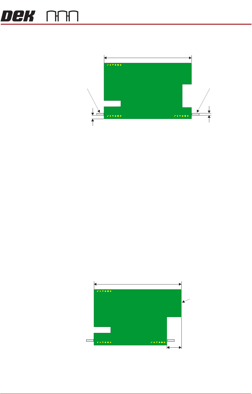
Board Cut-Outs The board length dimension programmed into the software sets the distance
between the inroad vane and the board stop vane.
The distance between the two vanes might be different to the board length in
the following circumstances:
• The board has cut-outs that coincide with the vanes
• The board is not square or rectangular
• The board has rounded or chamfered corners
If the board length is present where the vanes contact the board, as in the
graphic above, the remainder of this section may be ignored.
The board length dimension programmed into the software must be the overall
length of the board. Any cut-outs that coincide with the board stop vane or the
inroad vane must be compensated for using the Leading Edge Cut Out or
Trailing Edge Cut Out parameters.
The Leading Edge Cut Out parameter compensates for any difference between
the right hand side of the board and the point that the board stop vane contacts
the board, if different. The parameter is adjustable from 0.0mm to 50.0mm in
0.1mm increments.
Plan View on Board
Board Length
Board Stop VaneInroad Vane
2.5mm (nominal)
1.5mm (nominal)
Plan View on Board
Board Length
Leading Edge
Leading Edge Cut Out
RAPID TRANSIT CONVEYOR (RTC) MODULE
OVERVIEW
22.8 Technical Reference Manual Chapter Issue 4, Aug 14
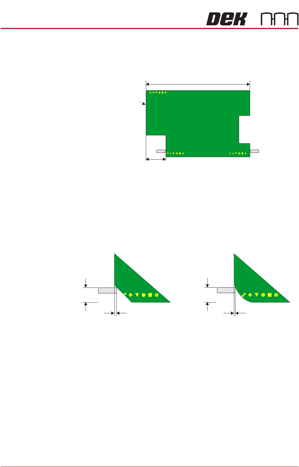
The Trailing Edge Cut Out parameter compensates for any difference between
the left hand side of the board and the point that the inroad vane contacts the
board, if different. The parameter is adjustable from 0.0mm to half the board
length in 0.1mm increments.
To prevent the board turning and jamming in the rails, ensure that the remaining
front and rear edges of the board (board length minus cut outs) are 50mm or
greater.
Chamfered or
Rounded Corners
If either the inroad or board stop vanes contact with a chamfered or rounded
corner, this must be treated as a cut out.
Boards with chamfered or rounded corners may jam in the rails if the vanes
contact directly with the chamfering or rounding, pushing the board towards the
rear rail.
Plan View on Board
Board Length
Trailing Edge
Trailing Edge Cut Out
Plan View on Board
4.0mm
(nominal)
4.0mm
(nominal)
Trailing Edge Cut Out Trailing Edge Cut Out
RAPID TRANSIT CONVEYOR (RTC) MODULE
OVERVIEW
Chapter Issue 4, Aug 14 Technical Reference Manual 22.9
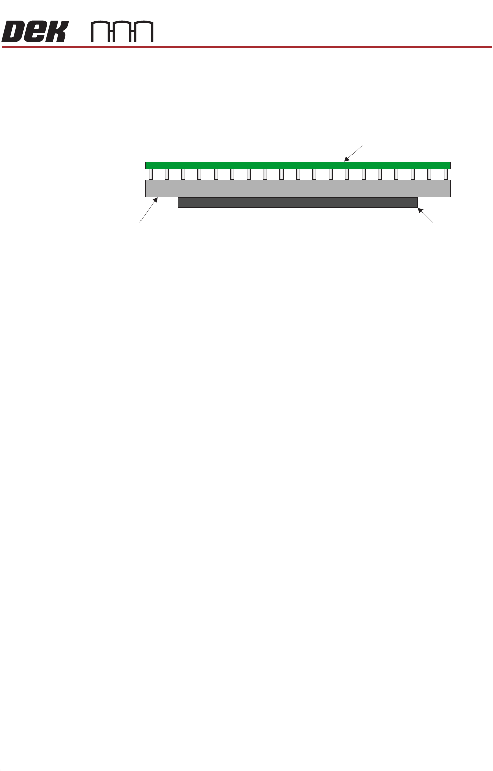
RTC Rising Table The RTC system uses the standard rising table mechanism but incorporates a
smaller manual tooling plate and different home vane.
The manual tooling plate measures 295mm from left to right and the maximum
board length is 375mm. Therefore, any boards greater than 295mm in length
must be supported using dedicated or Grid-Lok tooling.
The tooling locating dowel holes on the rising table are located in a different
position to the standard rising table. For more information refer to the Vacuum
Box Tooling section of the Board Support Tooling Module.
The rising table home vane on the RTC machine ensures that the home position
is 10mm higher than a standard machine.
The rails on the RTC machine are 5mm lower than a standard machine
(measured from the stencil), that combined with the rising table home position
means that the maximum under board clearance is reduced by 15mm to 27mm
(25mm available in software to allow for adequate clearance).
NOTE
For tooling options see the board support tooling chapter.
Board
Tooling Manual Tooling Plate