192277 - Micron Technical Reference Volume 3 - 第210页
FOREIGN MACHINE INTERFAC E FMI POD 33.8 Technical Reference Manual Chapter Issue 5, Aug 14 Figure 33-8 Fuji Upline Extension Cable Figure 33-9 Fuji Downline Extensio n Cable View on Arrow A 1 3 4 8 2 Pin 1 - Board Reques…
FOREIGN MACHINE INTERFACE
FMI POD
Chapter Issue 5, Aug 14 Technical Reference Manual 33.7
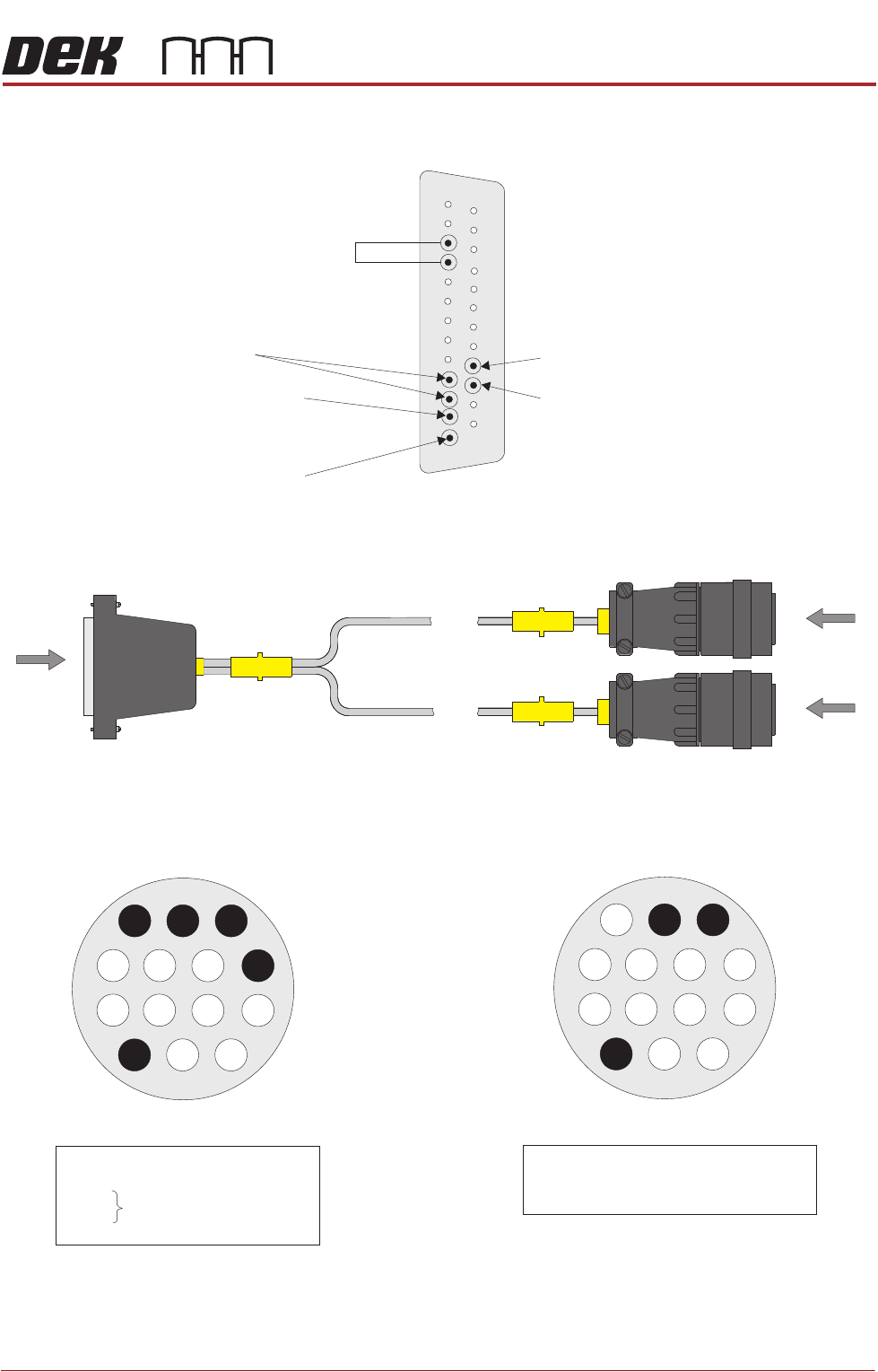
Fuji Interface
Figure 33-7 Fuji Interface Cable
View on Arrow A
View on Arrow B
1
14
4
8
2
View on Arrow C
14
1
2
4
8
Pin 1 - Board Request (H) (Downline)
Pin 2 - Board Request (L) (Downline)
Pin 14 - Shield
B
C
SK A Upline
SK B Downline
A
M28PL02
DEK Machine
25 Way D-type
Upline /Downline Sockets
AMP 206043-3
Pin 16 - Board Request (H) (Downline)
Pin 17 - Board Request (L) (Downline)
Pin 2 - Board Request (L) (Upline)
Pin 3 and Pin 4 - Linked in the Upline
Extension Cable (informs the DEK M/C
that FMI hardware is fitted)
0V
Pin 1 - Board Request (H) (Upline)
1
14
25
13
Pin 1 - Board Request (H) (Upline)
Pin 2 - Board Request (L) (Upline)
Pin 3 -
Pin 4 -
Pin 14 - Shield
Link
FOREIGN MACHINE INTERFACE
FMI POD
33.8 Technical Reference Manual Chapter Issue 5, Aug 14
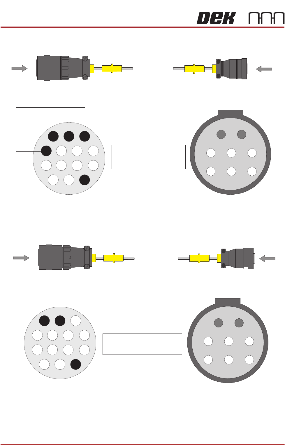
Figure 33-8 Fuji Upline Extension Cable
Figure 33-9 Fuji Downline Extension Cable
View on Arrow A
1
3
4
8
2
Pin 1 - Board Request (H)
Pin 2 - Board Request (L)
Pin 14 - Shield (PLA)
A
Up Plug
PL A
AMP 206044-1
B
Fuji Upline Plug
AMP 206434-1
View on Arrow B
1
2
3
5
6
8
0V
View on Arrow A
1
3
4
8
2
Pin 1 - Board Request (H)
Pin 2 - Board Request (L)
Pin 14 - Shield (AMP 206044-1)
A
Down Plug
PL B
AMP 206044-1
View on Arrow B
B
Fuji Downline Plug
AMP 206434-1
1
2
3
5
6
8
FOREIGN MACHINE INTERFACE
FMI POD
Chapter Issue 5, Aug 14 Technical Reference Manual 33.9
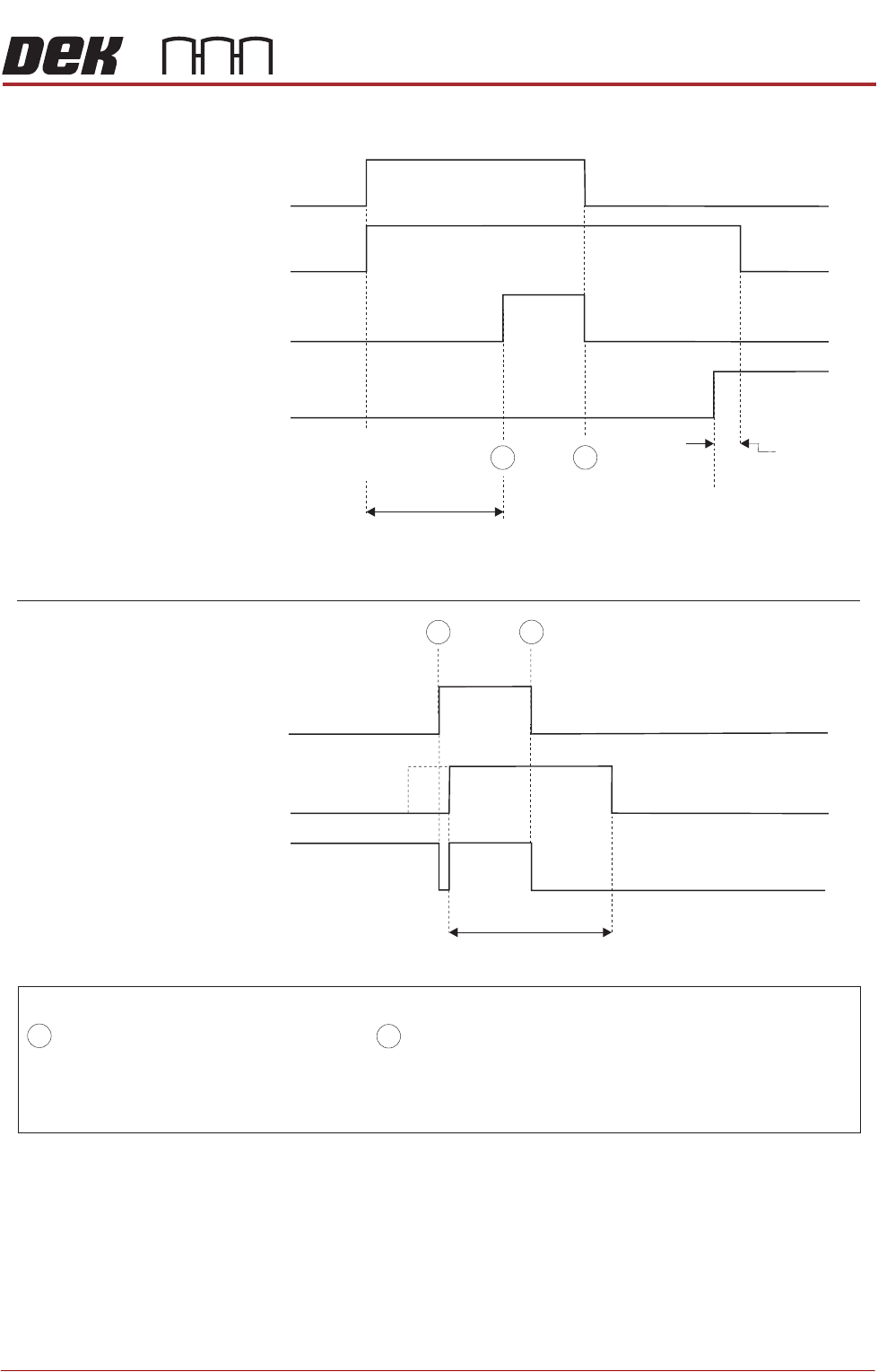
Figure 33-10 Fuji Logical Timing Diagram
NOTES
The Board Request signal is checked when a board becomes available at the previous stage. If the Board Request
signal is not present, a board is not transferred. The Board Request signal is output continuously to the previous
stage until the board arrives. No Board Request signal from the next stage indicates that the board has arrived
at the next stage.
- Board Trailing Edge at Sensor
- Board Leading Edge at Sensor
A
B
DEK M/C Output Sensor
Downline M/C
(I/P to DEK M/C)
Board Request
Downline
DEK M/C Belts Running
A
B
DEK M/C Input Sensor
DEK M/C
(O/P from DEK M/C)
Board Request
DEK M/C Board At Stop Sensor
DEK M/C Ready
Start Belts
Board At Stop
Transfer Complete
< Transfer Period
< Transfer Period
Belt Overrun
Upline
DEK M/C Belts Running
A
B