192277 - Micron Technical Reference Volume 3 - 第215页
FOREIGN MACHINE INTERFACE FMI POD Chapter Issue 5, Aug 14 Technical Reference Manual 33.13 Figure 33-14 Panasonic Logical T iming Diagram NOTES The Board Request signal is checked when a board becomes available at the pr…
FOREIGN MACHINE INTERFACE
FMI POD
33.12 Technical Reference Manual Chapter Issue 5, Aug 14
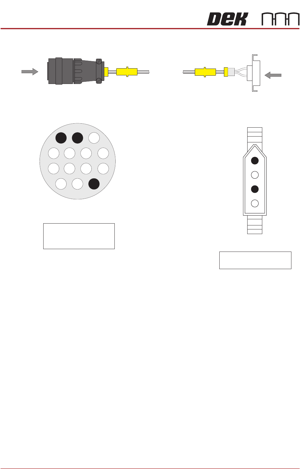
Figure 33-13 Panasonic Downline Extension Cable
View on Arrow A
1
3
4
8
2
Pin 1 - Board Request (H)
Pin 2 - Board Request (L)
Pin 14 - Shield
A
Down Plug
PL B
AMP 206044-1
View on Arrow B
3
1
Pin 1 - Board Request (L)
Pin 3 - Board Request (H)
B
Panasonic
Downline Plug
4 Pin Molex
FOREIGN MACHINE INTERFACE
FMI POD
Chapter Issue 5, Aug 14 Technical Reference Manual 33.13
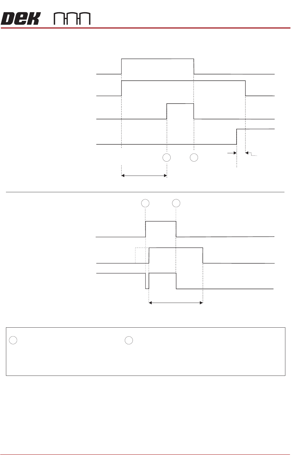
Figure 33-14 Panasonic Logical Timing Diagram
NOTES
The Board Request signal is checked when a board becomes available at the previous stage. If the Board Request
signal is not present, a board is not transferred. The Board Request signal is output continuously to the previous
stage until the board arrives. No Board Request signal from the next stage indicates that the board has arrived
at the next stage.
- Board Trailing Edge at Sensor
- Board Leading Edge at Sensor
A
B
DEK M/C Output Sensor
Downline M/C
(I/P to DEK M/C)
Board Request
Downline
DEK M/C Belts Running
A
B
DEK M/C Input Sensor
DEK M/C
(O/P from DEK M/C)
Board Request
DEK M/C Board At Stop Sensor
DEK M/C Ready
Start Belts
Board At Stop
Transfer Complete
< Transfer Period
< Transfer Period
Belt Overrun
Upline
DEK M/C Belts Running
A
B
FOREIGN MACHINE INTERFACE
MULTI-INTERFACE UNIT
33.14 Technical Reference Manual Chapter Issue 5, Aug 14
MULTI-INTERFACE UNIT
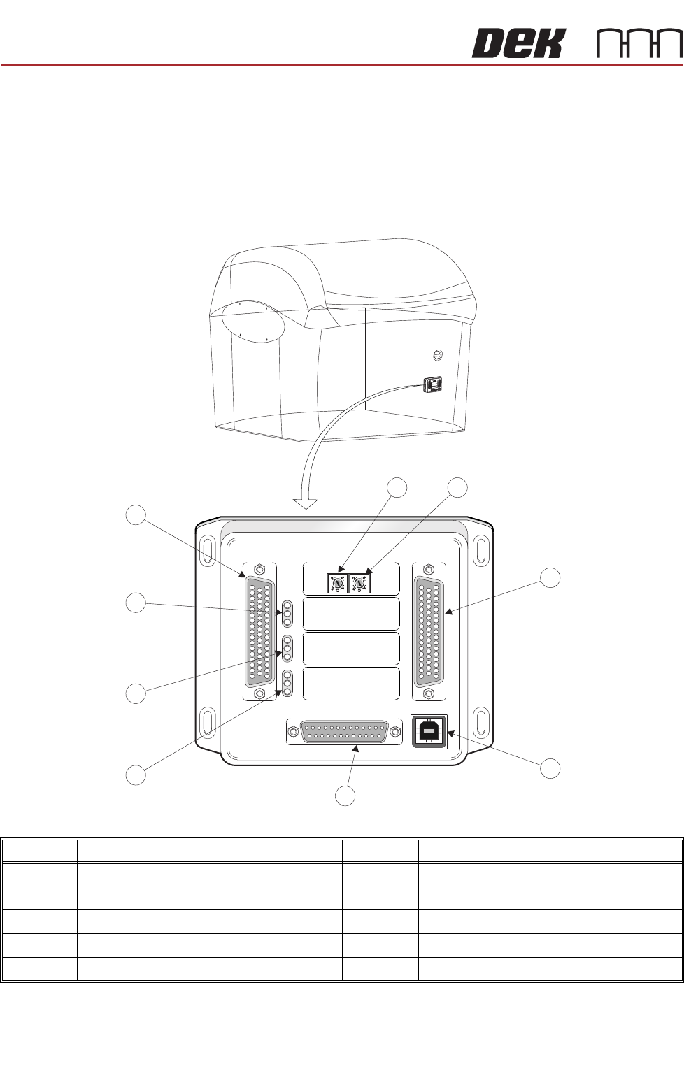
The Multi-Interface Unit (MIU) is a communications interface that allows DEK
Printing Machines to communicate with upline and downline board handlers.
The MIU is mounted on the services panel behind the rear panel of the machine
and connects to the M36 Machine Controller for its power supplies and input/
output signals.
Item Description Item Description
1 Upline Protocol Selection Switch 6 Output Indicator LED’s
2 Downline Protocol Selection Switch 7 Input Indicator LED’s
3 M1SK02 Downline Connector 8 Power Supply LED’s
4 M1SK04 USB Connector (not used) 9 M1SK01 Upline Connector
5 M1PL03 Power Supply Connector
M
1
S
K
1
M
1
SK1
U
P
L
I
N
E
UPL
INE
M
1
S
K
2
M1
S
K2
D
O
W
N
L
I
N
E
DOW
NLI
N
E
M
1
P
L
3
M
1PL
3
D
E
K
M
/
C
DEK
M/
C
M
1
S
K
4
M1S
K
4
D
E
K
U
S
B
DE
K
U
SB
+
1
2
V
+
1
2
V
+
2
4
V
+2
4V
+
2
4
V
S
W
+
2
4V
SW
S
E
N
D
U
P
L
I
N
E
S
E
ND
UP
LI
NE
S
E
N
D
D
O
W
N
L
I
N
E
SEN
D
DOWN
L
INE
C
O
N
T
R
O
L
I
N
CONTR
O
LIN
U
P
L
I
N
E
R
E
A
D
Y
U
PL
IN
E
R
EA
D
Y
D
O
W
N
L
I
N
E
R
E
A
D
Y
DOW
N
L
I
N
E
R
E
A
DY
C
O
N
T
R
O
L
O
U
T
C
O
NTR
O
LOUT
P
O
W
E
R
P
OWE
R
I
/
P
'
S
I
/
P
'
S
O
/
P
'
S
O
/P'
S
P
ROT
O
C
O
L
SE
L
E
C
T
ION
P
R
O
TO
C
OLSEL
E
C
T
I
O
N
U
P
UP
L
I
N
E
L
I
N
E
D
O
W
N
DOW
N
L
I
N
E
L
I
NE
MI
U
1
91
114MIU 191114
4
8
0
4
8
0
M1SK1
UPLINE
M1SK2
DOWNLINE
M1PL3
DEK M/C
M1SK4
DEK USB
+12V
+24V
+24V SW
SEND UPLINE
SEND DOWNLINE
CONTROL IN
UPLINE READY
DOWNLINE READY
CONTROL OUT
POWER
I/P'S
O/P'S
PROTOCOL SELECTION
UP
LINE
DOWN
LINE
MIU 191114
4
80
4
80
1 2
3
4
5
6
7
8
9