192277 - Micron Technical Reference Volume 3 - 第233页
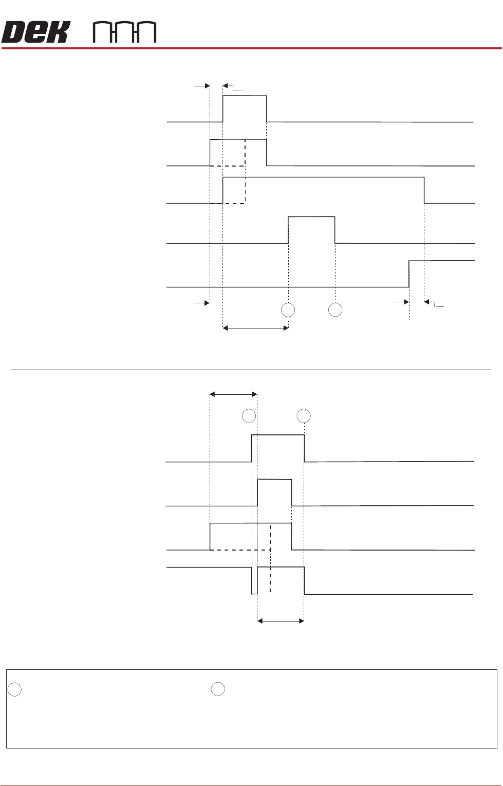
FOREIGN MACHINE INTERFACE MULTI-INTERFACE UNIT Chapter Issue 5, Aug 14 Technical Reference Manual 33.31 Figure 33-29 TDK Logical T iming Diagram DEK M/C Input Sensor Upline M/C (I/P to DEK M/C) Ready DEK M/C (O/P from DE…
FOREIGN MACHINE INTERFACE
MULTI-INTERFACE UNIT
33.30 Technical Reference Manual Chapter Issue 5, Aug 14
TDK Interface
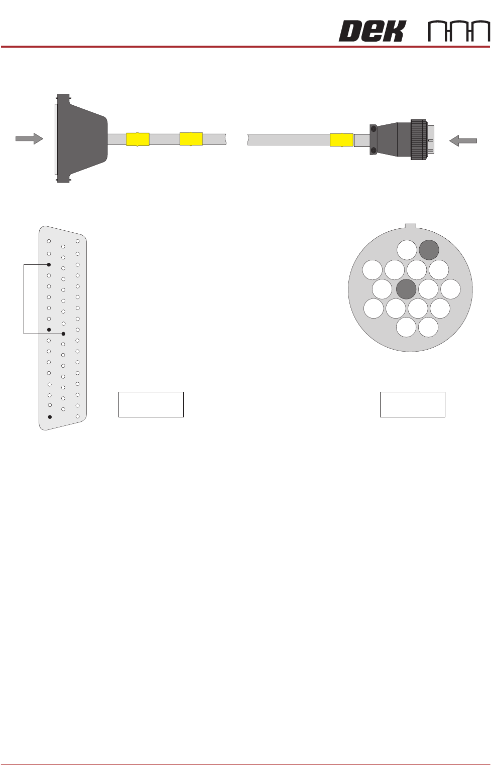
Figure 33-28 TDK Upline/Downline Interface Cable
B
PLB
A
PLA
DEK Machine
50 Way D-type
TDK
16W Upline/Downline Plug
View on Arrow B
21
3
7
9
15
16
14
10
6
Pin 1 - Ready
Pin 9 - Start
Pin 1 - Start
Pin 9 - Ready
View on Arrow A
33
25
15
50
1
18
34
17
9
FOREIGN MACHINE INTERFACE
MULTI-INTERFACE UNIT
Chapter Issue 5, Aug 14 Technical Reference Manual 33.31
Figure 33-29 TDK Logical Timing Diagram
DEK M/C Input Sensor
Upline M/C
(I/P to DEK M/C)
Ready
DEK M/C
(O/P from DEK M/C)
Start
DEK M/C Board At Stop Sensor
DEK M/C
Ready
Board At Stop
Transfer Complete
< Transfer Period
< Transfer Period
< Transfer Period
< Transfer Period
Belt Overrun
Upline
DEK M/C Belts Running
A
NOTES
The 'Ready' and 'Start' signals are independent of each other and either signal may be switched on first (contacts
closed). A board transfer occurs when both the 'Ready' and 'Start' signal are switched on (contacts closed). The
'Ready' and 'Start' signals are switched off (contacts open) 500msecs after both signals are switched on (contacts
closed).
- Board Trailing Edge at Sensor
- Board Leading Edge at Sensor
A
B
Downline
Downline M/C
(I/P to DEK M/C)
Ready
DEK M/C Belts Running
DEK M/C Output Sensor
DEK M/C
(O/P from DEK M/c)
Start
A
B
B
FOREIGN MACHINE INTERFACE
MULTI-INTERFACE UNIT
33.32 Technical Reference Manual Chapter Issue 5, Aug 14
Fuji Interface
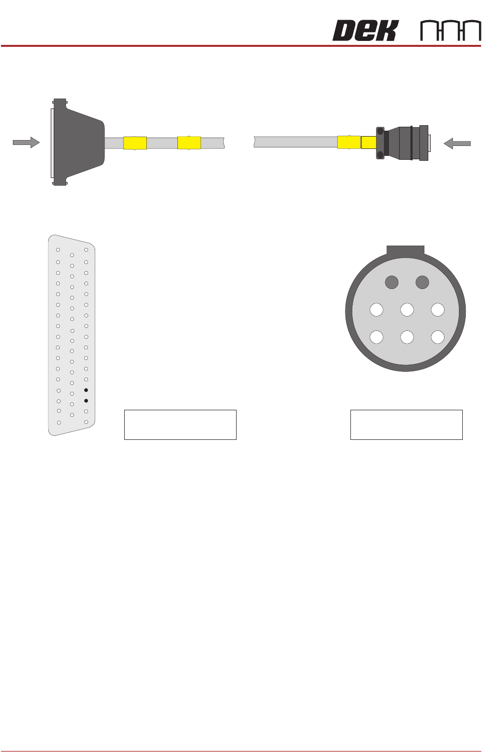
Figure 33-30 Fuji Upline Interface Cable
View on Arrow B
B
Fuji Upline Plug
AMP 206434-1
PLB
1
2
3
5
6
8
A
PLA
DEK Machine
50 Way D-type
Pin 1 - Board Request (H)
Pin 2 - Board Request (L)
Pin 36 - Board Request (L)
Pin 37 - Board Request (H)
View on Arrow A
33
37
36
50
1
18
34
17