192277 - Micron Technical Reference Volume 3 - 第239页
FOREIGN MACHINE INTERFACE MULTI-INTERFACE UNIT Chapter Issue 5, Aug 14 Technical Reference Manual 33.37 Figure 33-35 Panasonic Logical T iming Diagram NOTES The Board Request signal is checked when a board becomes availa…
FOREIGN MACHINE INTERFACE
MULTI-INTERFACE UNIT
33.36 Technical Reference Manual Chapter Issue 5, Aug 14
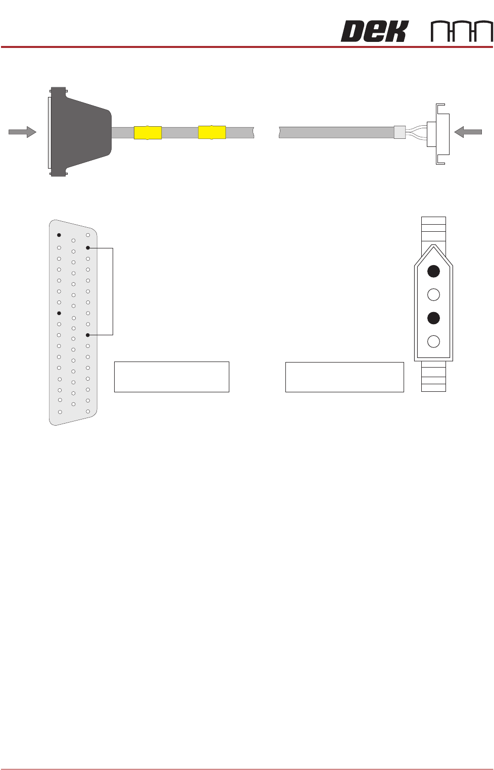
Figure 33-34 Panasonic Downline Interface Cable
View on Arrow B
B
PLB
Panasonic
Downline Plug
4 Pin Molex
A
PLA
DEK Machine
50 Way D-type
Pin 1 - Board Request (L)
Pin 3 - Board Request (H)
1
3
Pin 10 - Board Request (H)
Pin 17 - Board Request (L)
View on Arrow A
33
10
41
50
1
18
34
17
49
FOREIGN MACHINE INTERFACE
MULTI-INTERFACE UNIT
Chapter Issue 5, Aug 14 Technical Reference Manual 33.37
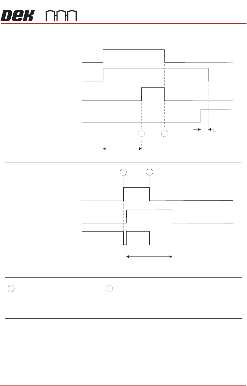
Figure 33-35 Panasonic Logical Timing Diagram
NOTES
The Board Request signal is checked when a board becomes available at the previous stage. If the Board Request
signal is not present, a board is not transferred. The Board Request signal is output continuously to the previous
stage until the board arrives. No Board Request signal from the next stage indicates that the board has arrived
at the next stage.
- Board Trailing Edge at Sensor
- Board Leading Edge at Sensor
A
B
DEK M/C Output Sensor
Downline M/C
(I/P to DEK M/C)
Board Request
Downline
DEK M/C Belts Running
A
B
DEK M/C Input Sensor
DEK M/C
(O/P from DEK M/C)
Board Request
DEK M/C Board At Stop Sensor
DEK M/C Ready
Start Belts
Board At Stop
Transfer Complete
< Transfer Period
< Transfer Period
Belt Overrun
Upline
DEK M/C Belts Running
A
B
FOREIGN MACHINE INTERFACE
MULTI-INTERFACE UNIT
33.38 Technical Reference Manual Chapter Issue 5, Aug 14
Sanyo Interface
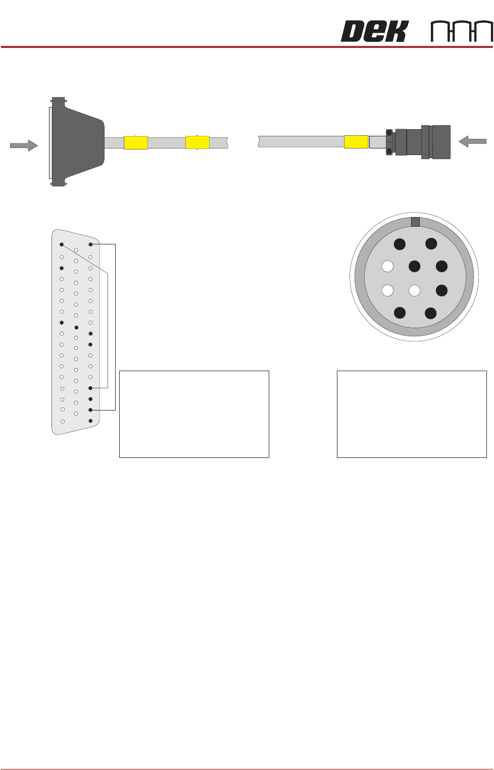
Figure 33-36 Sanyo Upline Interface Cable
PLB
A
PLA
DEK Machine
50 Way D-type
View on Arrow B
Pin 1 - Output Machine Run Signal
Pin 2 - Output Machine PCB
Requirement Signal
Pin 3 - Run Signal
Pin 4 - PCB Transfer Signal
Pin 5 - Ready Signal
Pin 8 - VLED In (+24V)
Pin 9 - VLED Out (+24V)
Pin 10 - Run Signal
Pin 15 - VLED Out (+24V)
Pin 26 - Ready Signal
Pin 34 - Output Machine PCB
Requirement Signal
Pin 36 - Output Machine Run Signal
Pin 41 - VLED In (+24V)
Pin 42 - PCB Transfer Signal
1
2
3
4
7
8
9
10
5
6
B
Sanyo Upline Plug
View on Arrow A
33
10
42
41
50
1
18
34
35
36
37
17
15
26