192277 - Micron Technical Reference Volume 3 - 第24页
RAPID TRANSIT CONVEYOR (RTC) MODULE ADJUSTMENTS AND SETTINGS 22.12 Technical Reference Manual Chapter Issue 4, Aug 14 5. If adjustment is not required, go to th e next sectio n - Rear Rail Parallelism. 6. T o adjust the …
RAPID TRANSIT CONVEYOR (RTC) MODULE
ADJUSTMENTS AND SETTINGS
Chapter Issue 4, Aug 14 Technical Reference Manual 22.11
ADJUSTMENTS AND SETTINGS
Rising Table Home
Setting
To check and adjust the rising table home setting, refer to the Rising Table
Module of this manual.
Parallelism
WARNING
BOARD CLAMPS. EXTREME CARE MUST BE EXERCISED WHEN WORKING IN
THE TOOLING AREA OF THE MACHINE TO AVOID INJURY. THE FOILS ON THE
FRONT AND REAR BOARD CLAMPS ARE VERY SHARP.
Parallelism of the print station rails and the camera X axis requires the Rail
Setting Jig (187652).
Front Rail
Parallelism
1. To move the vanes clear of the front print station rails, set the board length
to maximum and home the transport mechanism.
2. Home the RTC rails and set the rising table to vision height.
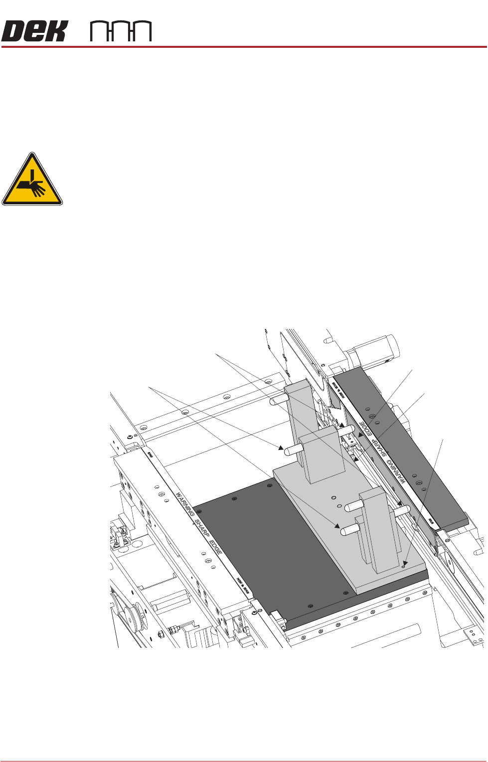
3. Fit the rail setting jig to the manual tooling plate locating the two dowels in
to the holes on the tooling plate.
NOTE
The rail setting jig must not exert any force on the front rail during placement.
If any force is felt, remove the jig, loosen the front print station rail securing
screws as described in Step 6, refit the jig and continue with Steps 7 to 9.
4. Using a 0.05mm feeler as a NO-GO gauge, check that the stops on the rail
setting jig abut the board support plate on the front print station rail.
Board Support Plate
Rail Setting Jig
Locating Dowel
(in 2 positions)
Rear Rail Stops
Front Rail Stops
RAPID TRANSIT CONVEYOR (RTC) MODULE
ADJUSTMENTS AND SETTINGS
22.12 Technical Reference Manual Chapter Issue 4, Aug 14
5. If adjustment is not required, go to the next section - Rear Rail Parallelism.
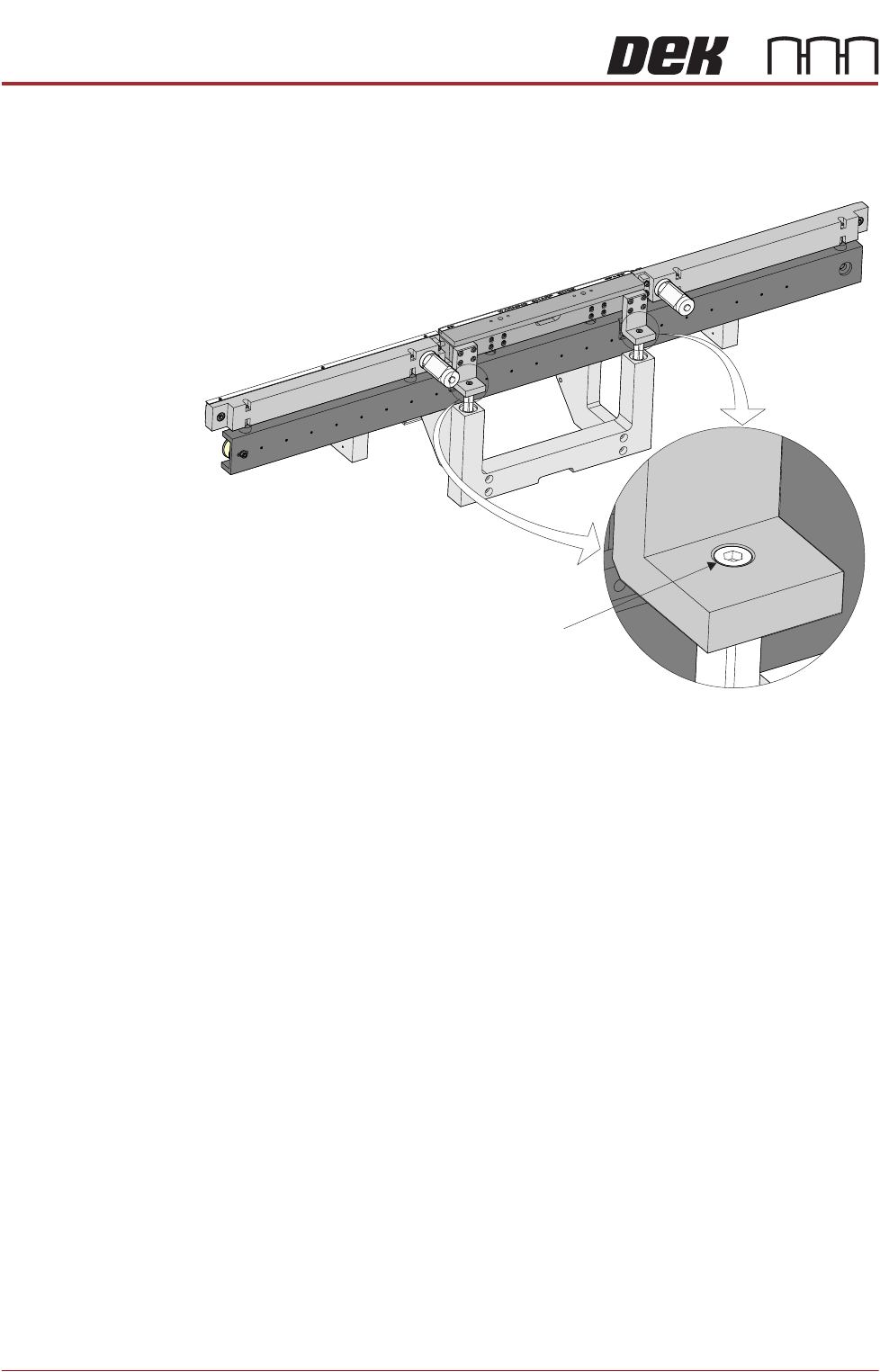
6. To adjust the front print station rail parallelism, loosen the two front print
station rail securing screws.
NOTE
The securing screws need to be loosened just enough to allow the rail to be
moved.
7. Move the front print station rails so that the front print station rail abuts both
stops on the jig without any pressure.
8. Tighten the securing screws.
9. Repeat Steps 4 to 8 until parallelism is achieved.
Rear Rail
Parallelism
NOTE
Front rail parallelism must be carried out before this procedure.
1. Using the drive belt, manually move the rear rail so that the rear print station
rail abuts the two stops on the rail setting jig without any pressure.
2. Using a 0.05mm feeler as a NO-GO gauge, check that no gap exists
between the stops and the board support plate.
3. If adjustment is not required, manually move the rear rail away from the jig
and remove the jig from the rising table.
4. To adjust the parallelism of the rear print station rail, the board clamp must
be removed.
Front Print Station Rail Securing Screw
(in 2 positions)

RAPID TRANSIT CONVEYOR (RTC) MODULE
ADJUSTMENTS AND SETTINGS
Chapter Issue 4, Aug 14 Technical Reference Manual 22.13
5. Remove the two board clamp securing screws using a flat bladed screw-
driver.
6. Remove the board clamp to access the rail securing screws.
7. Loosen the two rail securing screws.
NOTE
The securing screws need to be loosened just enough to allow the rail to be
moved.
8. Move the rear print station rails so that the rear print station rail abuts both
stops on the jig without any pressure.
NOTE
If parallelism cannot be achieved with the slack available, check that the rail
width drive belt has not jumped a tooth on one of the drive cogs.
9. Tighten the securing screws.
10. Using a 0.05mm feeler as a NO-GO gauge, check that no gap exists
between the stops and the board support plate.
11. Repeat Steps 7 to 10 until parallelism is achieved.
12. Refit the board clamp.
13. Manually move the rear rail away from the jig and remove the jig from the
rising table.
Plan View of Print Station Rail
Board Clamp Securing Screws
Plan View of Print Station Rail
Rail Securing Screw Rail Securing Screw