192277 - Micron Technical Reference Volume 3 - 第241页
FOREIGN MACHINE INTERFACE MULTI-INTERFACE UNIT Chapter Issue 5, Aug 14 Technical Reference Manual 33.39 Figure 33-37 Sanyo Downline Interface Cable B Sanyo Downline Plug PLB A PLA DEK Machine 50 W ay D-type View on Arrow…
FOREIGN MACHINE INTERFACE
MULTI-INTERFACE UNIT
33.38 Technical Reference Manual Chapter Issue 5, Aug 14
Sanyo Interface
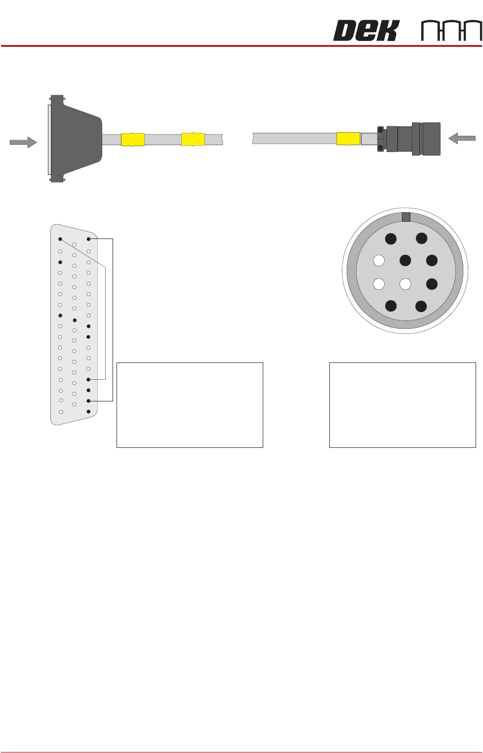
Figure 33-36 Sanyo Upline Interface Cable
PLB
A
PLA
DEK Machine
50 Way D-type
View on Arrow B
Pin 1 - Output Machine Run Signal
Pin 2 - Output Machine PCB
Requirement Signal
Pin 3 - Run Signal
Pin 4 - PCB Transfer Signal
Pin 5 - Ready Signal
Pin 8 - VLED In (+24V)
Pin 9 - VLED Out (+24V)
Pin 10 - Run Signal
Pin 15 - VLED Out (+24V)
Pin 26 - Ready Signal
Pin 34 - Output Machine PCB
Requirement Signal
Pin 36 - Output Machine Run Signal
Pin 41 - VLED In (+24V)
Pin 42 - PCB Transfer Signal
1
2
3
4
7
8
9
10
5
6
B
Sanyo Upline Plug
View on Arrow A
33
10
42
41
50
1
18
34
35
36
37
17
15
26
FOREIGN MACHINE INTERFACE
MULTI-INTERFACE UNIT
Chapter Issue 5, Aug 14 Technical Reference Manual 33.39
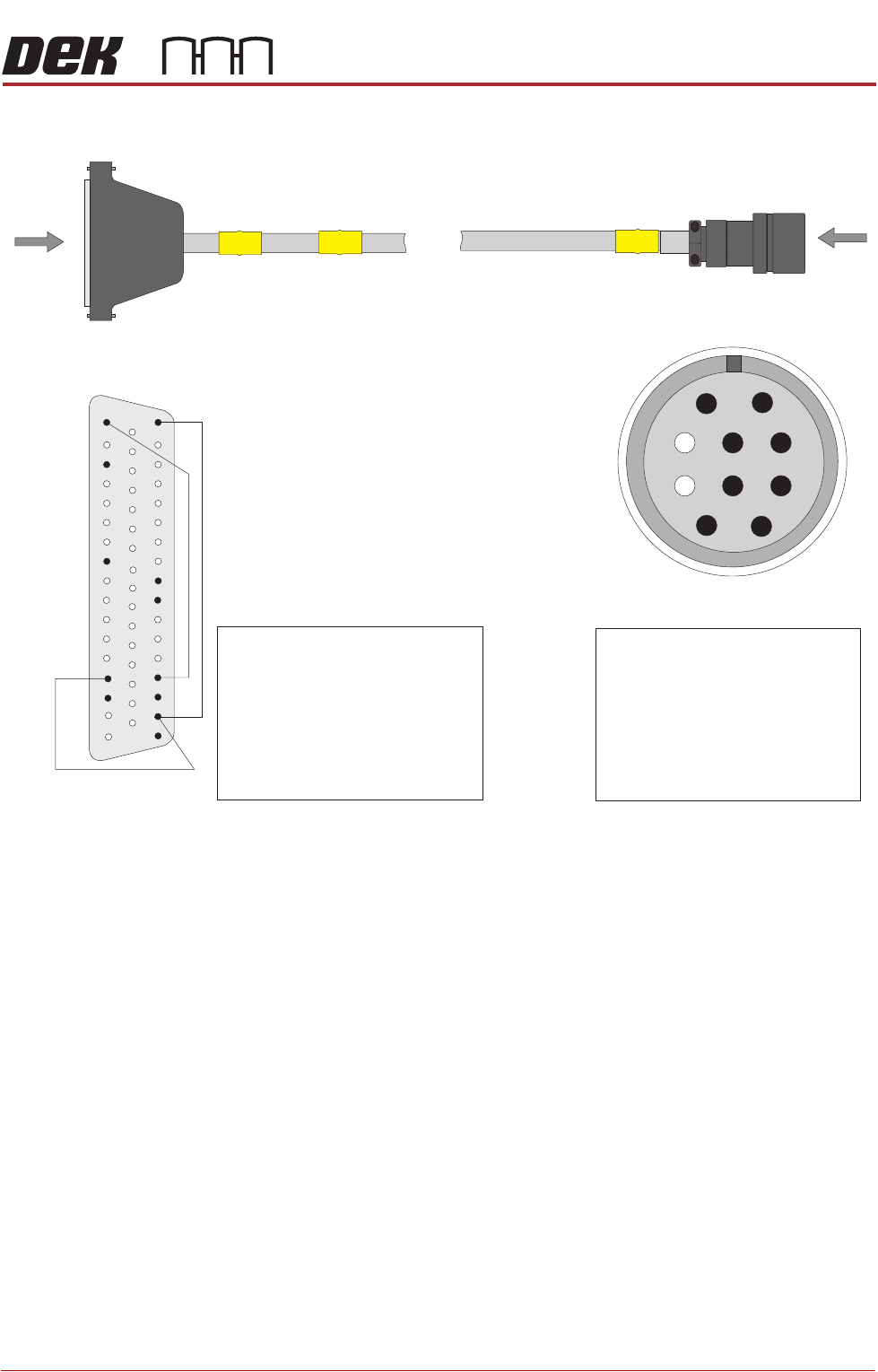
Figure 33-37 Sanyo Downline Interface Cable
B
Sanyo Downline Plug
PLB
A
PLA
DEK Machine
50 Way D-type
View on Arrow B
Pin 1 - Run Signal
Pin 2 - PCB Requirement Signal
Pin 3 - Input Machine Run Signa
Pin 4 - Input Machine PCB
Transfer Signal
Pin 5 - Input Machine Ready Signal
Pin 8 - VLED In (+24V)
Pin 9 - VLED Out (+24V)
Pin 10 - GND
1
2
3
4
7
8
9
10
5
6
Pin 3 - Input Machine Ready Signal
Pin 10 - Run Signal
Pin 15 - VLED Out (+24V)
Pin 26 - Ready Signal
Pin 34 - Input Machine PCB
Transfer Signal
Pin 36 - Input Machine Run Signal
Pin 41 - VLED In (+24V)
Pin 42 - PCB Requirementr Signal
View on Arrow A
3
10
42
41
50
1
18
34
35
36
37
17
15
FOREIGN MACHINE INTERFACE
MULTI-INTERFACE UNIT
33.40 Technical Reference Manual Chapter Issue 5, Aug 14
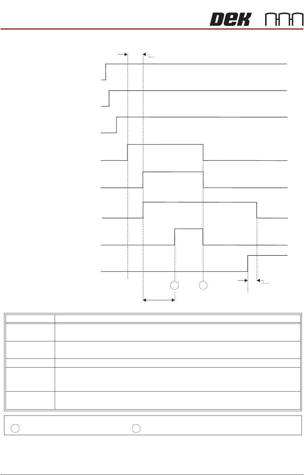
Figure 33-38 Sanyo Upline Logical Timing Diagram
Upline M/C
(I/P to DEK M/C)
Run Signal
DEK M/C
(O/P from DEK M/C)
O/P M/C
Run Signal
DEK M/C
(O/P from DEK M/C)
O/P M/C PCB
Requirement Signal
Upline M/C
(I/P to DEK M/C)
Ready Signal
Upline M/C
(I/P to DEK M/C)
PCB Transfer
Signal
DEK M/C Belts Running
DEK M/C Input Sensor
DEK M/C Board At Stop Sensor
DEK M/C
Ready
Board At Stop
Transfer Complete
< Transfer Period
Belt Overrun
< Transfer Period
A
B
- Board Trailing Edge at Sensor
- Board Leading Edge at Sensor
A
B
NOTES
This signal informs the printer that the upline machine is in automatic operation. When
this signal is off, the printer stops after completing the current board.
Run Signal
OM/P /C
Run Signal
Ready Signal
OM/P /C
PCB Requirement
Signal
PCB Transfer
Signal
This signal shows that the upline machine is transferring a board. Upon receipt of this
signal the printer starts the belts to take in the board.
This signal informs the upline machine that the printer is ready to receive a board. A
board transfer is only possible when this signal is on.
This signal shows that the upline machine is ready to start processing a board.
This signal informs the upline machine that the printer is in automatic operation, ie
initialized.
Signal Name Definition