192277 - Micron Technical Reference Volume 3 - 第244页
FOREIGN MACHINE INTERFAC E MULTI-INTERFACE UNIT 33.42 Technical Reference Manual Chapter Issue 5, Aug 14
FOREIGN MACHINE INTERFACE
MULTI-INTERFACE UNIT
Chapter Issue 5, Aug 14 Technical Reference Manual 33.41
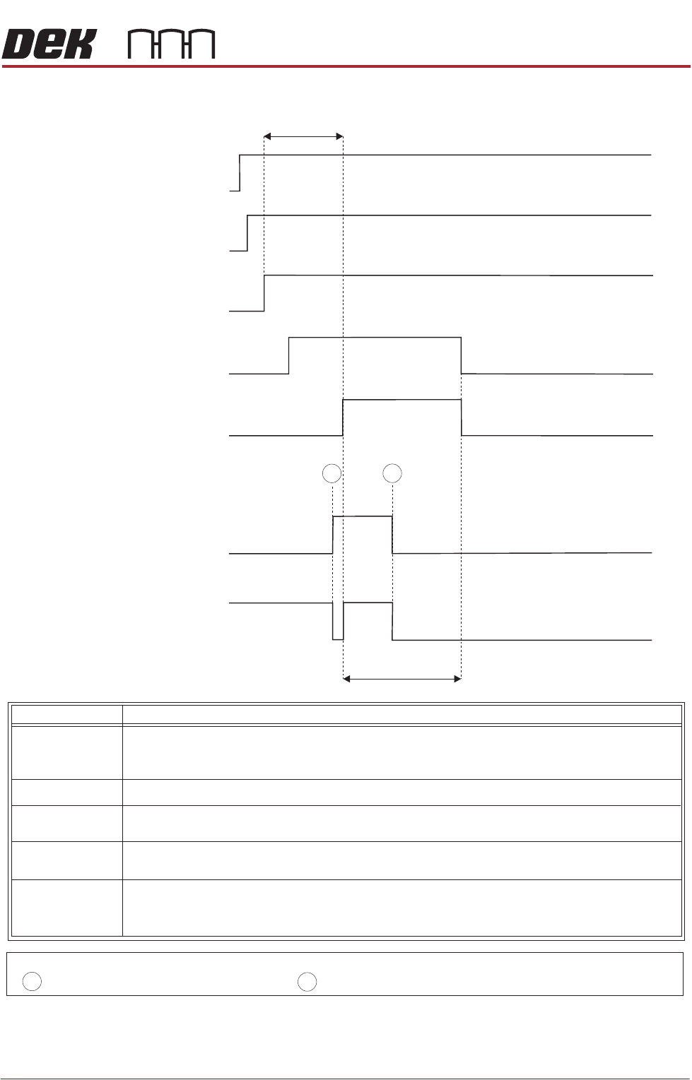
Figure 33-39 Sanyo Downline Logical Timing Diagram
Downline M/C
(I/P to DEK M/C)
Downline M/C
(I/P to DEK M/C)
I/P M/C
Run Signal
DEK M/C
(O/P from DEK M/C)
DEK M/C
(O/P from DEK M/C)
DEK M/C
(O/P from DEK M/C)
Run Signal
PCB Requirement
Signal
I/P M/C
Ready Signal
I/P M/C PCB
Transfer Signal
- Board Trailing Edge at Sensor
- Board Leading Edge at Sensor
A
B
NOTES
DEK M/C Belts Running
DEK M/C Output Sensor
< Transfer Period
< Transfer Period
A
B
This signal informs the downline machine that the printer is in automatic operation, ie
initialized. When this signal is off, the downline machine stops after completing the
current board.
IM/P /C
Run Signal
Run Signal
IM/P /C
Ready Signal
PCB Requirement
Signal
IM/P /C
PCB Transfer
Signal
This signal shows that the printer is transferring a board. Upon receipt of this signal
the downline machine starts the belts to take in the board.
This signal informs the printer that the downline is ready to receive a board. A board
transfer is only possible when this signal is on.
This signal shows that the printer is ready to start processing a board.
This signal informs the printer that the downline machine is in automatic operation.
Signal Name Definition

FOREIGN MACHINE INTERFACE
MULTI-INTERFACE UNIT
33.42 Technical Reference Manual Chapter Issue 5, Aug 14
MAN MACHINE INTERFACE
OVERVIEW
Chapter Issue 11, Jan 17 Technical Reference Manual 34.1
CHAPTER 34 MAN MACHINE INTERFACE
OVERVIEW
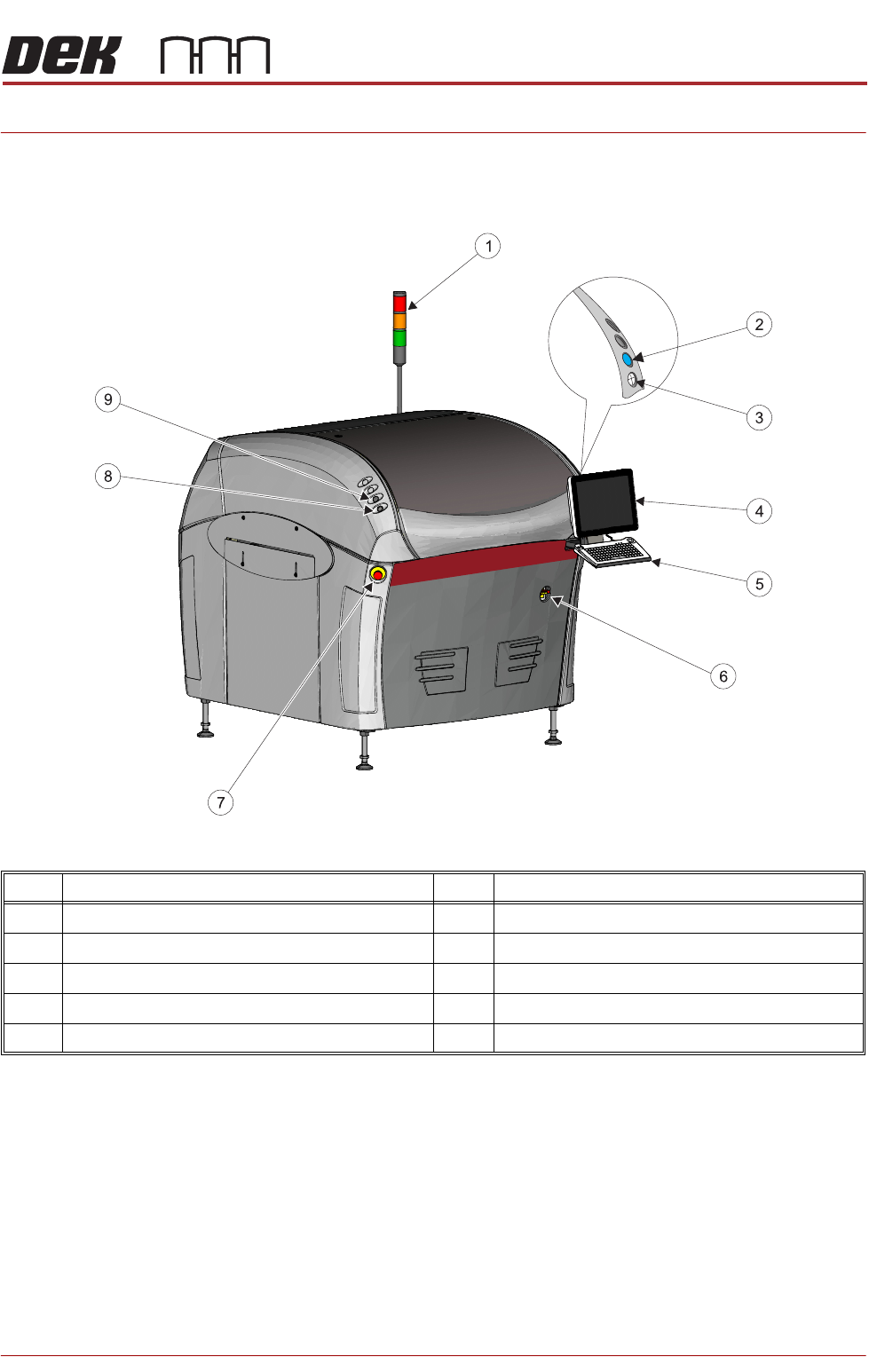
Figure 34-1 Type 1 Covers
Item Description Item Description
1 Tricolour Beacon 6 Mains Isolator Switch
2 System Button 7 E Stop Button
3 Jog Button (Right) 8 Jog Button (Left)
4 Monitor 9 Internal Lighting Switch
5 Keyboard/Trackball Mouse