192277 - Micron Technical Reference Volume 3 - 第262页
MAN MACHINE I NTERFACE ADJUSTMENTS AND SETTINGS 34.18 Technical Reference Manual Chapter Issue 11, Jan 17 IR Keyboard/ Mouse Frequency Setting (T ype 1 Cover) NOTE The combination setting for each printer is facto ry set…
MAN MACHINE INTERFACE
ADJUSTMENTS AND SETTINGS
Chapter Issue 11, Jan 17 Technical Reference Manual 34.17
ADJUSTMENTS AND SETTINGS
Monitor Bracket
Adjustments (Type
1 Cover)
NOTE
The monitor may sustain damage if any of the adjustment locking mechanisms
are released without supporting the monitor.
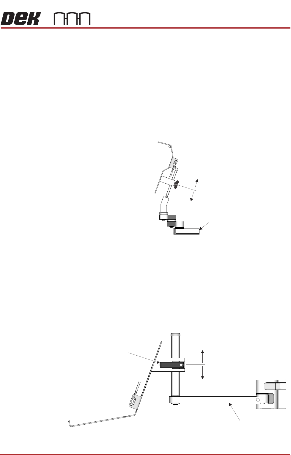
The monitor bracket has the following adjustments to optimise the viewing angle
of the monitor:
• The monitor arm has three swivel joints allowing the monitor to be swiv-
elled to any position and extended or retracted in relation to the printer.
• The monitor bracket has a sliding height adjustment which is secured by a
thumb screw. The height variation is ±48mm from the central position.
Monitor Bracket
Adjustments (Type
2 and 4 Covers)
NOTE
The monitor may sustain damage if the adjustment locking mechanism is
released without supporting the monitor.
The monitor bracket has the following adjustments to optimise the viewing angle
of the monitor:
• The monitor arm has two swivel joints allowing the monitor to be swivelled
to any position.
• The monitor arm has a sliding height adjustment which is secured by a
release catch. The height variation is ±70mm from the central position.
±48mm
Monitor Arm
±70mm
Release Catch
Monitor Arm
MAN MACHINE INTERFACE
ADJUSTMENTS AND SETTINGS
34.18 Technical Reference Manual Chapter Issue 11, Jan 17
IR Keyboard/
Mouse Frequency
Setting (Type 1
Cover)
NOTE
The combination setting for each printer is factory set and logged onto the
printer Configuration and Despatch documentation. This combination is also
recorded onto a ASM database for each printer serial number. ASM must be
informed of any change to the set combination.
The IR keyboard and mouse has a combination of 16 settings which can be
changed for the following reasons:
• Adjacent machine frequency conflict.
• Keyboard/Mouse unit replacement.
Carry out the following procedure to change the frequency combination setting:
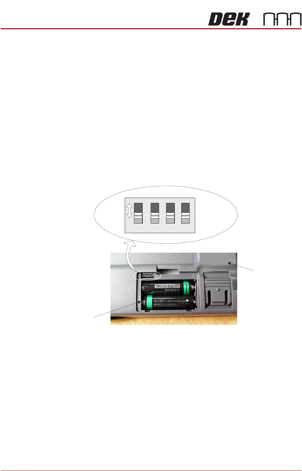
1. Turn the hand held IR keyboard/mouse upside down.
2. Unclip and remove the battery compartment panel. A four way bit switch is
located in the top left hand corner of the battery compartment, figure below
refers.
3. Using a suitable tool (eg instrument screwdriver) move the four bit switches
to any of the 16 configurations (each switch has two positions, the figure
above shows all four switches in the forward position).
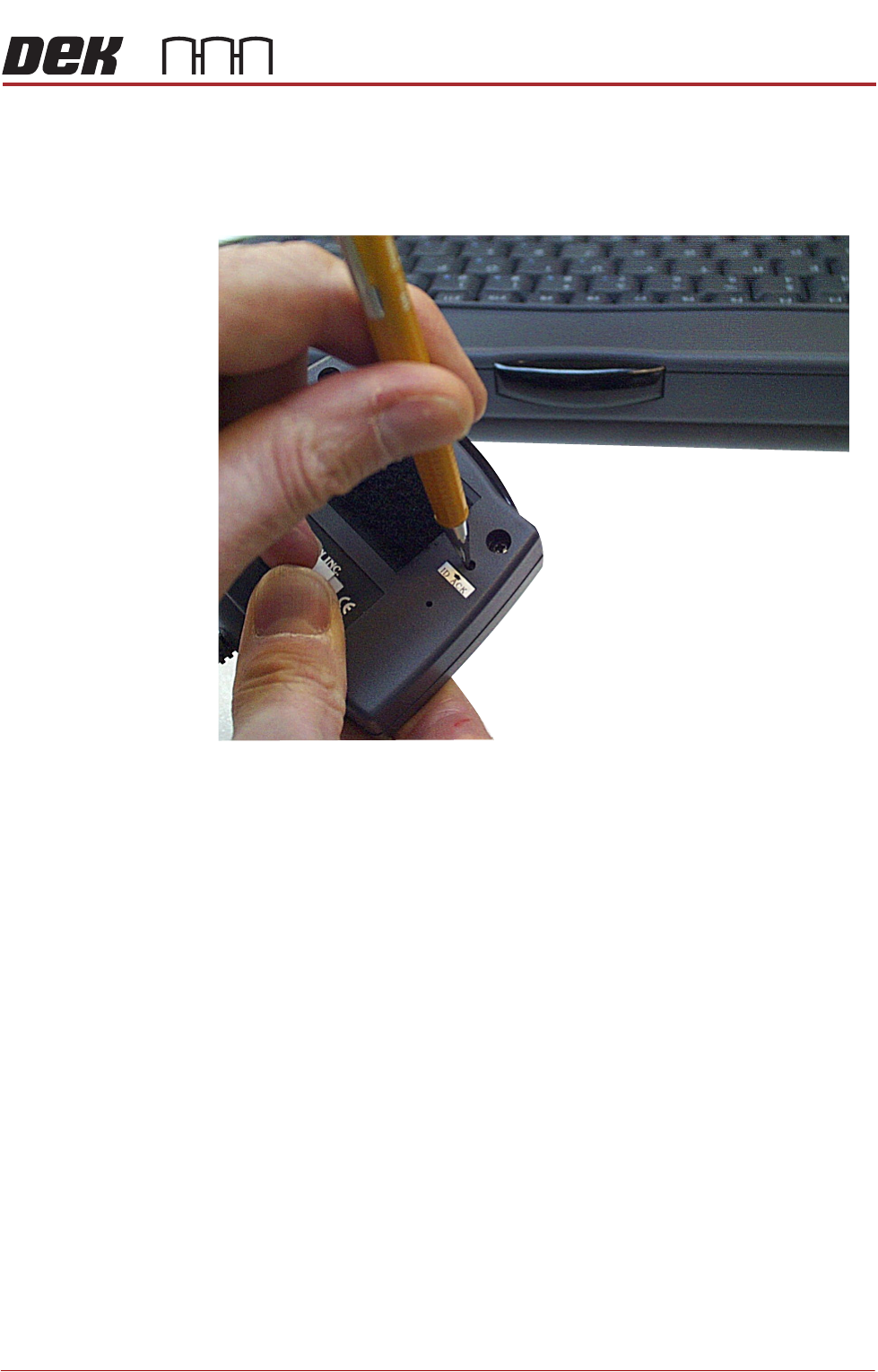
4. When a switch setting is made the IR receiver unit has to be set to recognise
the new keyboard configuration.
5. Remove the IR receiver unit from above the monitor (held by velcro fastener)
for access to the ID_ACK button on the underside of the unit, figure overleaf
refers.
Underside of IR
Keyboard/Mouse
Battery
Compartment
1 2 3 4
ON
Bit Switches
MAN MACHINE INTERFACE
ADJUSTMENTS AND SETTINGS
Chapter Issue 11, Jan 17 Technical Reference Manual 34.19
6. Using a small instrument screwdriver or similar, press the ID-ACK button on
the underside of the receiver unit. The receiver interrogates the host key-
board/mouse, (the frequency combination of the keyboard unit is dedicated
to the receiver unit).
NOTE
Ensure that the IR keyboard/mouse is aimed at the IR receiver and is within
five metre range.
7. Re-position the IR receiver above the monitor.
The keyboard/mouse is now ready for use.