192277 - Micron Technical Reference Volume 3 - 第269页
PNEUMATIC MODULE OVERVIEW Chapter Issue 7, Aug 14 Technical Reference Manual 35.3 Print Carriage Solenoids The number of solenoids varies from printer to pr inter depending on which options are fitted to the prin ter . T…
PNEUMATIC MODULE
OVERVIEW
35.2 Technical Reference Manual Chapter Issue 7, Aug 14
WARNING
COMPRESSED AIR. COMPRESSED AIR SHOULD NEVER IMPINGE UPON THE
BODY. PORTS, PIPES, ETC MUST NEVER BE BLOCKED BY HAND. BEFORE
CONNECTING OR DISCONNECTING ANY PNEUMATIC COMPONENTS, ENSURE
THE COMPRESSED AIR SUPPLY HAS BEEN DISSIPATED AND DISCONNECTED
FROM THE MACHINE.
The mains air supply to the DEK printer should be between 5 bar and 8 bar.
The air should be to quality class 2.3.3, where:
2 (dirt) = 1 micron or less
3 (water) = -20°C pressure dew point
3 (oil) = 1mg/m3 or less
The mains air supply is filtered and regulated to 0.5MPa (5 bar) before being
sensed by the air pressure switch, which is set at 0.3MPa (3 bar) The com-
pressed air input is applied to the following:
• Printer Rear Solenoids
• Print Carriage Solenoids
• High Throughput Conveyors (HTC)
• Vacuum Tooling
• Grid-Lok Tooling
• Air Ionizer
The electrically activated solenoid valves provide pneumatic power through
several types of air cylinder.
Printer Rear
Solenoids
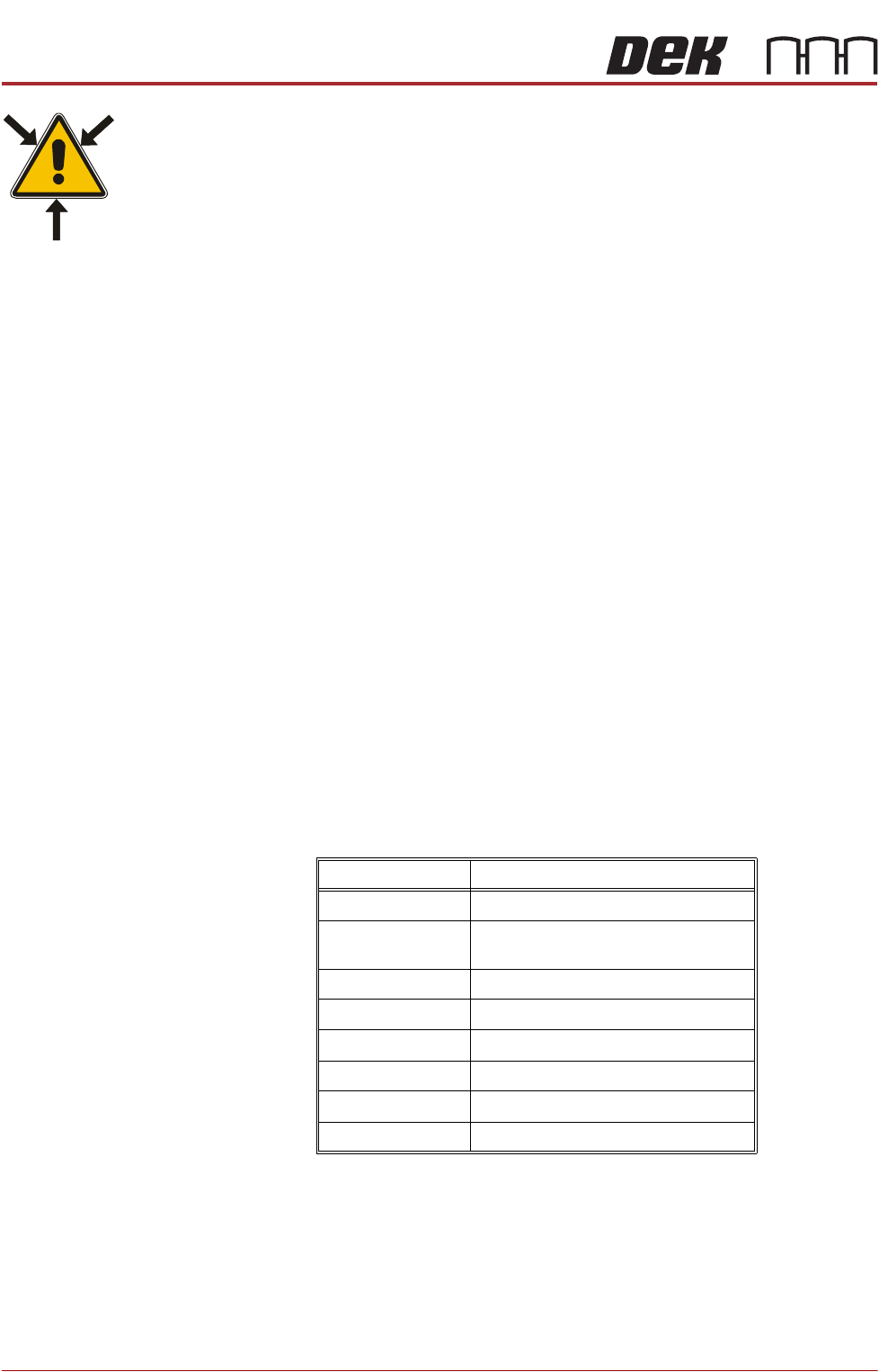
The number of solenoids varies from printer to printer depending on which
options are fitted to the printer. The solenoids are labelled with the solenoid
number for identification.
Solenoid Number Function
16SOL22 Rail Board Stop
16SOL14 Camera/Remote Board Stop
Rail Width Clamp (RTC Printer)
16SOL10 Board Clamps
16SOL08 Understencil Cleaner Squeegee Bar
16SOL07 Screen Clamps
16SOL31B Chase Clamps
16SOL31A Lid Bolt
16SOL03 Inroad Vane Lift (RTC Printer)

PNEUMATIC MODULE
OVERVIEW
Chapter Issue 7, Aug 14 Technical Reference Manual 35.3
Print Carriage
Solenoids
The number of solenoids varies from printer to printer depending on which
options are fitted to the printer. The electrical connections to the solenoids are
labelled with the solenoid number for identification.
Solenoid Number Function
9SOL29 Screen Load
9SOL28 Auto Drip Tray
9SOL27 Paste Dispenser Tilt
9SOL26 Paste Dispenser
9SOL25 ProFlow Paste
PNEUMATIC MODULE
ELECTRICAL SCHEMATIC
35.4 Technical Reference Manual Chapter Issue 7, Aug 14
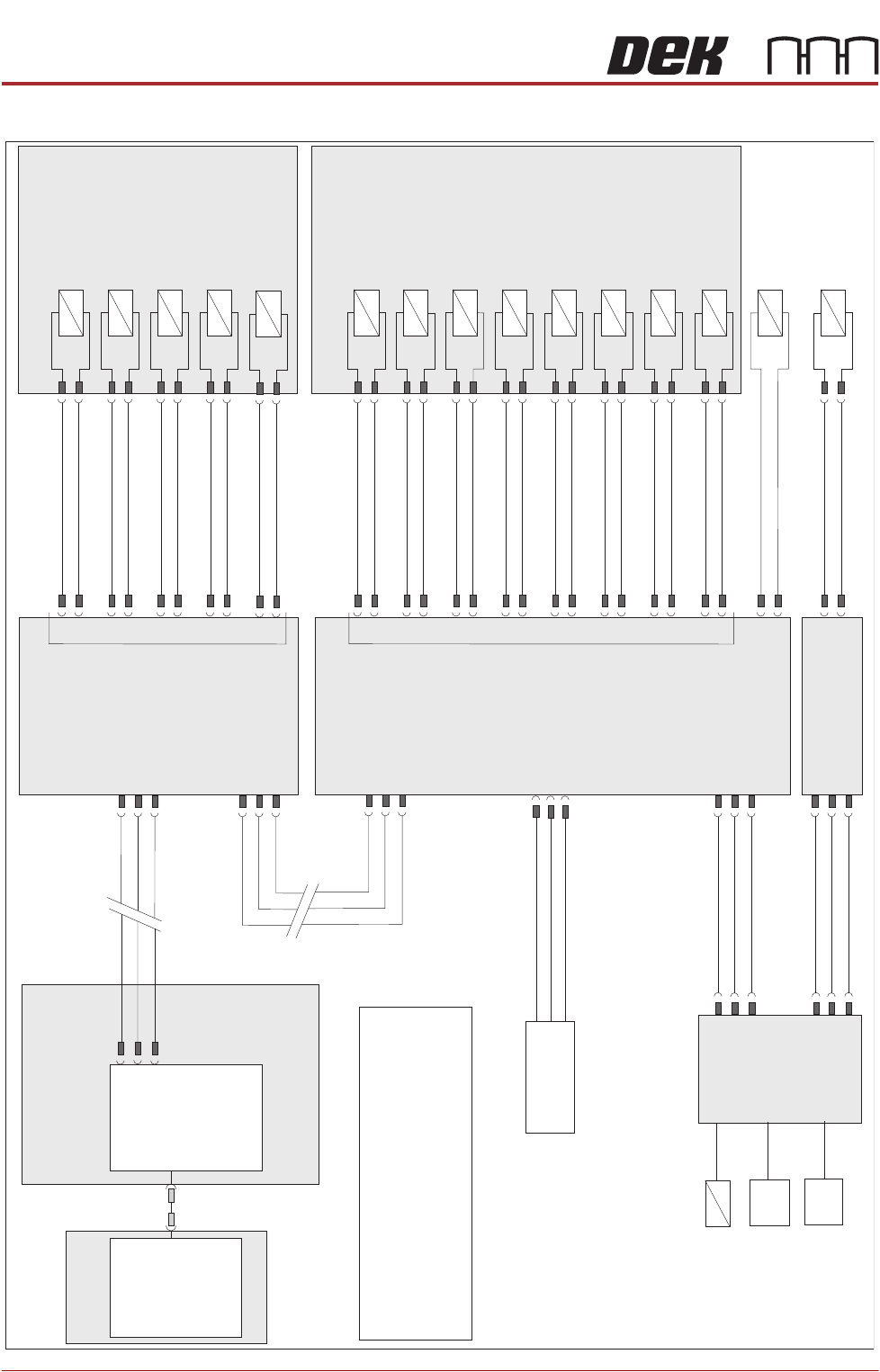
ELECTRICAL SCHEMATIC
M36 Machine
Control Enclosure
Main Machine
I/O Node 2
Screen Cleaner
I/O Node 4
N2PL7
N4SK6
1
2
3
DIG IN 0
Air Pressure SW
8SE11
OTS Control
Solenoids (6)
Clamp Pressure
Regulator
Snug Pressure
Regulator
+12V
Sig
0V
PC
USB
Motherboard
NextMove ES
(I/O Node 1)
1
2
4
CAN_H
CAN_L
CAN GND
M36PL35
CAN Bus
N3SK2
7
2
3
CAN In
CAN In
CAN In
N2SK2
N4SK2
N SK25
7
7
2
2
3
3
CAN Out
CAN Out
CAN Out
N3SK3
7
2
3
Print Carriage
I/O Node 3
N2SK3
N SK35
7
7
7
2
2
2
3
3
3
N3SK8
N2SK4
N2SK2
9SK28
Auto Drip Tray
9SOL28
DIG OUT 6
0V
4
12
9SK27
Paste Disp. Tilt
9SOL27
DIG OUT 5
0V
3
11
16SK22
Rail Board Stop
16SOL22
DIG OUT 12
0V
6
16
9SK26
Paste Disp.
9SOL26
DIG OUT 4
0V
2
10
9SK25
ProFlow Paste
9SOL25
DIG OUT 3
0V
1
9
16SK14
Board Stop/RTC
Rail Width Clamp
16SOL14
DIG OUT 10
0V
4
16
16SK10
Board Clamps
16SOL10
DIG OUT 9
0V
9
16
9SK29
Screen Load
9SOL29
DIG OUT 7
0V
5
13
16SK07
Screen Clamps
16SOL07
DIG OUT 8
0V
2
15
16SK31
Chase Clamps
16SOL31B
DIG OUT 7
0V
1
14
16SK08
USC Squeegee
16SOL08
DIG OUT 14
0V
9
21
16SK31
16SK03
Lid Bolt
16SOL31A
Inroad Vane Lift
(RTC Machine)
16SOL03
Venturi Vac Unit
(metal covers
machine only)
8SOL29
Venturi Vac Unit
8SOL24
DIG OUT 11
DIG OUT 0
DIG OUT 15
DIG OUT 3
0V
0V
0V
0V
5
1
22
1
14
2
23
2
Machine Rear Solenoids
Print Carriage Solenoids
NOTE
The breaks in the CAN Bus chain reflect that
additional I/O Nodes may be fitted, refer to
Machine Control chapter for the complete
CAN Bus chain.
OTS Option
I/O NODE 5