192277 - Micron Technical Reference Volume 3 - 第272页
PNEUMATIC MODULE PNEUMATIC SCHEMATICS 35.6 Technical Reference Manual Chapter Issue 7, Aug 14 Figure 35-2 Pneumatic Schematic Sheet 2 HTC Aux Conveyor Board Stops L-R= L/H D’Line Board Stop L-R= R/H UpLine Board Stop L-R…
PNEUMATIC MODULE
PNEUMATIC SCHEMATICS
Chapter Issue 7, Aug 14 Technical Reference Manual 35.5
PNEUMATIC SCHEMATICS
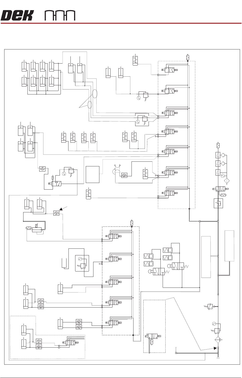
Figure 35-1 Pneumatic Schematic Sheet 1
To Grid-Lok Tooling
See Board Support
Tooling Chapter
Pneumatic Dump
Valve. Only fitted
to machines
with M39 EMO.
5/2
9SOL29
5/2
9SOL28
5/2
9SOL27
5/2
9SOL25
Screen Load
Actuator
A
B
ASM Rail Lock
Rail Clamps
Left
Rail Clamps
Right
Out
Paste Dispense
In
Reg/Assy
IN
HTC Aux. Conveyors
(optional) See Sheet 2
See Sheet 2
P
Out
R
Vacuum
Tooling
Venturi Vacuum Tooling (optional)
Pressure
Sense
Filter/Reg Assy
Mains
Air In
At 4.5 Bar
Minimum
3/2 Dual
16SOL31A
5/2
16SOL08
5/2
16SOL07
5/2
16SOL03
5/2
16SOL10
5/2
16SOL14
A
B
A
B
A
B
A
B
A
B
A
Lid Bolt
RTC Vane Clamp
Lift Sol/
Heavy Palete Rails
Snugger
ProFlow ATx Only
3/2 Dual
16SOL31B
B
5/2
9SOL26
A
B
Chase Clamps
Only one
connection
depending on type
'C' Chase/ASM
Screen Clamps
Standard - 8 Clamps
Machined C Chase - 4 Clamps
ASM Screen Clamps
Screen Clean
Squeegee Bar
(optional)
Proclean
Screen Clean
Squeegee Bar
(optional)
Board Clamps
Grid-Lok
Control
Unit
Machine Rear Solenoids
A
B
A
B
A
B
Print Carriage Solenoids
Auto Drip Tray
Paste Dispense
Tilt
ProFlow + SCAR
(optional)
5/2
9SOL28/29
A
B
Semi Auto Screen Load/
Screen Load Actuator
Board Clamp
Reg (optional)
In Out
Camera
Board Stop
Remote Board
Stop
PNEUMATIC MODULE
PNEUMATIC SCHEMATICS
35.6 Technical Reference Manual Chapter Issue 7, Aug 14
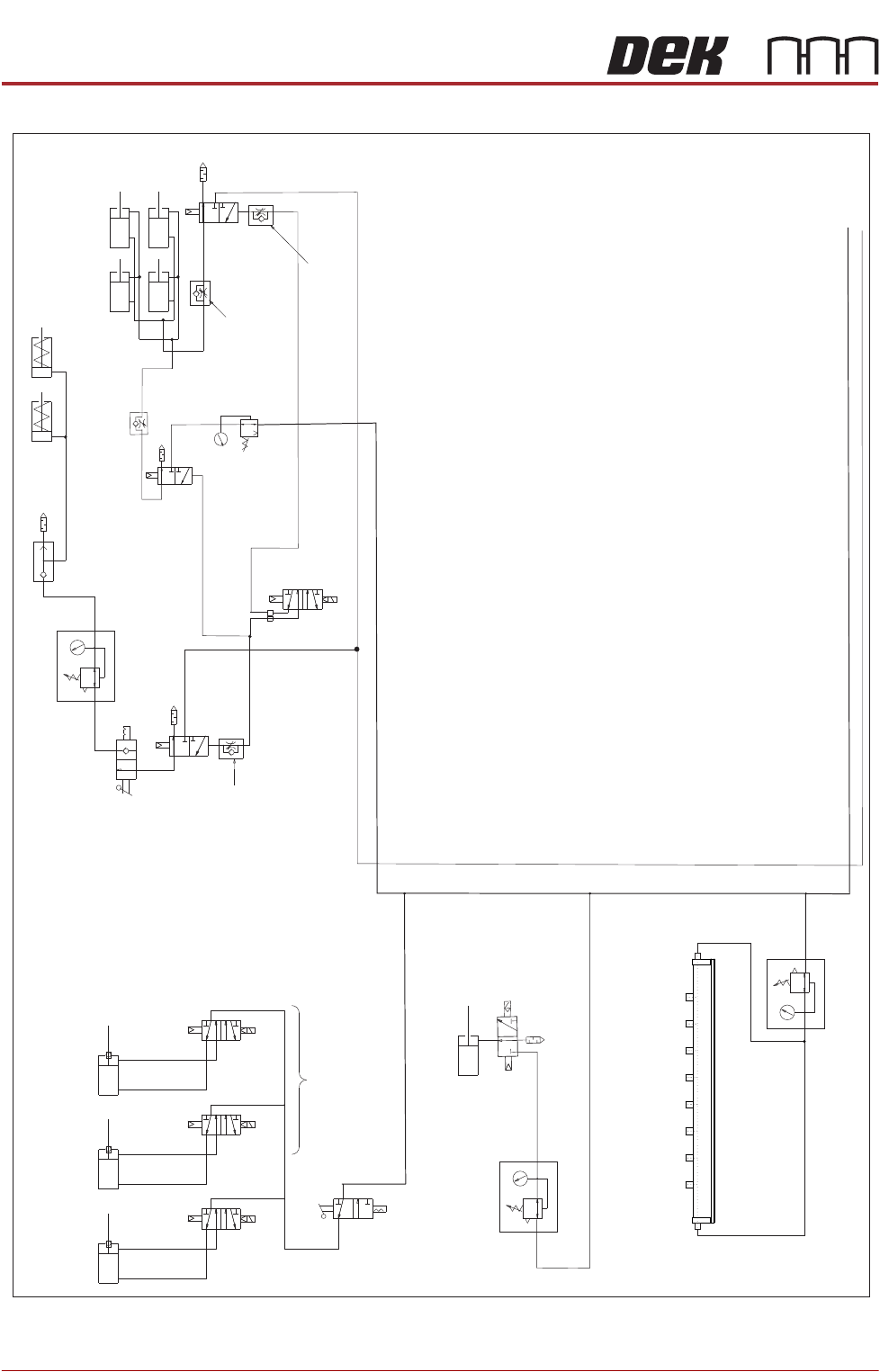
Figure 35-2 Pneumatic Schematic Sheet 2
HTC Aux Conveyor Board Stops
L-R=
L/H D’Line
Board Stop
L-R=
R/H UpLine
Board Stop
L-R=
R/H D’Line
Board Stop
Stinger Dispense
M27SOL02
M27SOL03
M27SOL01
R/H Conveyor
Solenoids
5/2
16SOL10
AB
Clamp
Speed
Control
Unclamp Delay Control
Fitted at Solenoid
Valve on Rear of M/C
Board Clamps
Snuggers Option
Snuggers
Out
Out
In
In
Pressure Control
Snuggers On
Stinger Option
Snugger
Delay
Control
Board Clamp
Reg (optional)
In
Out
Air Ionizer Option
Out
In
See Sheet 1
PNEUMATIC MODULE
ADJUSTMENTS AND SETTINGS
Chapter Issue 7, Aug 14 Technical Reference Manual 35.7
ADJUSTMENTS AND SETTINGS
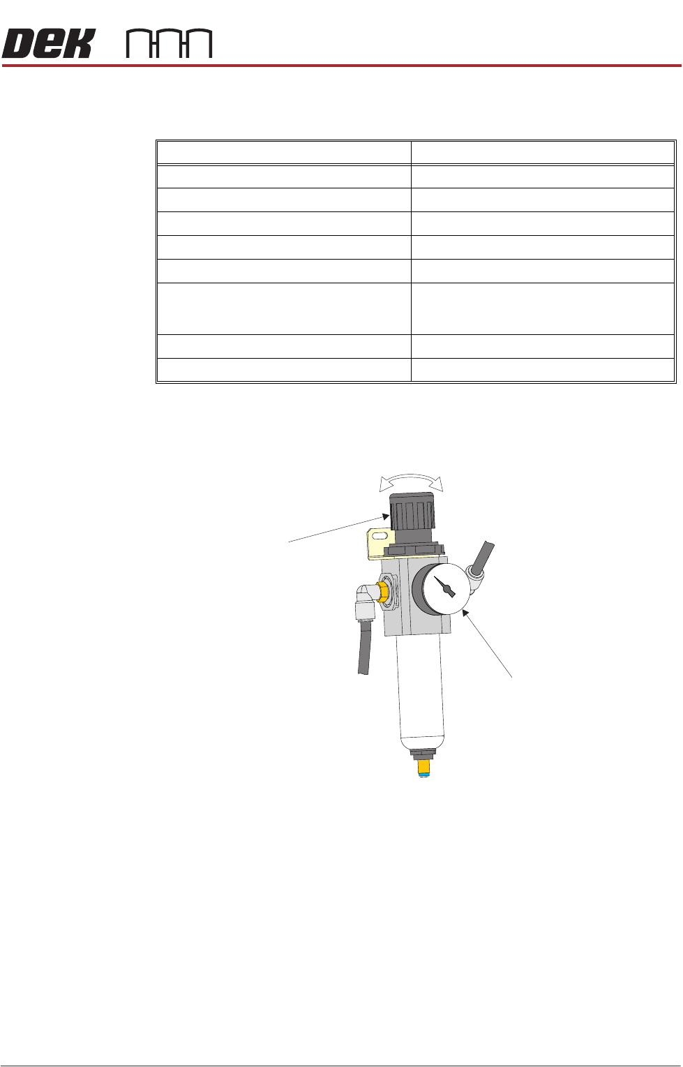
Pressure Switch
and Mains Air
Regulator Setting
1. Set the mains air regulator (black pointer) to 0.3MPa (3 bar) by turning the
regulator control valve, clockwise to increase the pressure and anti-clock-
wise to decrease it.
2. Turn the cover on the pressure sensor and gauge anti-clockwise and
remove.
3. Set the pressure sensor (green pointer) by using a screwdriver to turn the
brass set screw slowly until the tricoloured beacon changes from green to
red, clockwise to decrease the pressure and anti-clockwise to increase it.
When the tricoloured beacon just changes to red, the pressure sensor is
correctly set at 0.3MPa (3 bar).
4. Replace the cover on the pressure sensor and gauge and turn clockwise to
lock.
Regulator Setting
Mains Air Input 0.5MPa (5 bar)
Paste Dispenser 43 psi (3 bar) maximum
Snuggers 29 psi (2 bar) maximum
Chase Clamps see Chase Clamp Regulator Setting
Board Clamps 0.5MPa (5 bar) maximum
ProFlow - Software Regulator:
ProFlow Idle Paste
ProFlow Paste Pressure
0.2 bar
0.2 bar to 4 bar
ProFlow ATx (Paste Dispenser Regulator) 1.3 to 1.7 bar
Air Ionizer 0.175MPa (1.75 bar)
Regulator
Control
Valve
Pressure Sensor
and Gauge