192277 - Micron Technical Reference Volume 3 - 第28页
RAPID TRANSIT CONVEYOR (RTC) MODULE ADJUSTMENTS AND SETTINGS 22.16 Technical Reference Manual Chapter Issue 4, Aug 14 Rail to T able Height The rail to table height is f actory set and must not be adjusted. Board Clamp S…
RAPID TRANSIT CONVEYOR (RTC) MODULE
ADJUSTMENTS AND SETTINGS
Chapter Issue 4, Aug 14 Technical Reference Manual 22.15
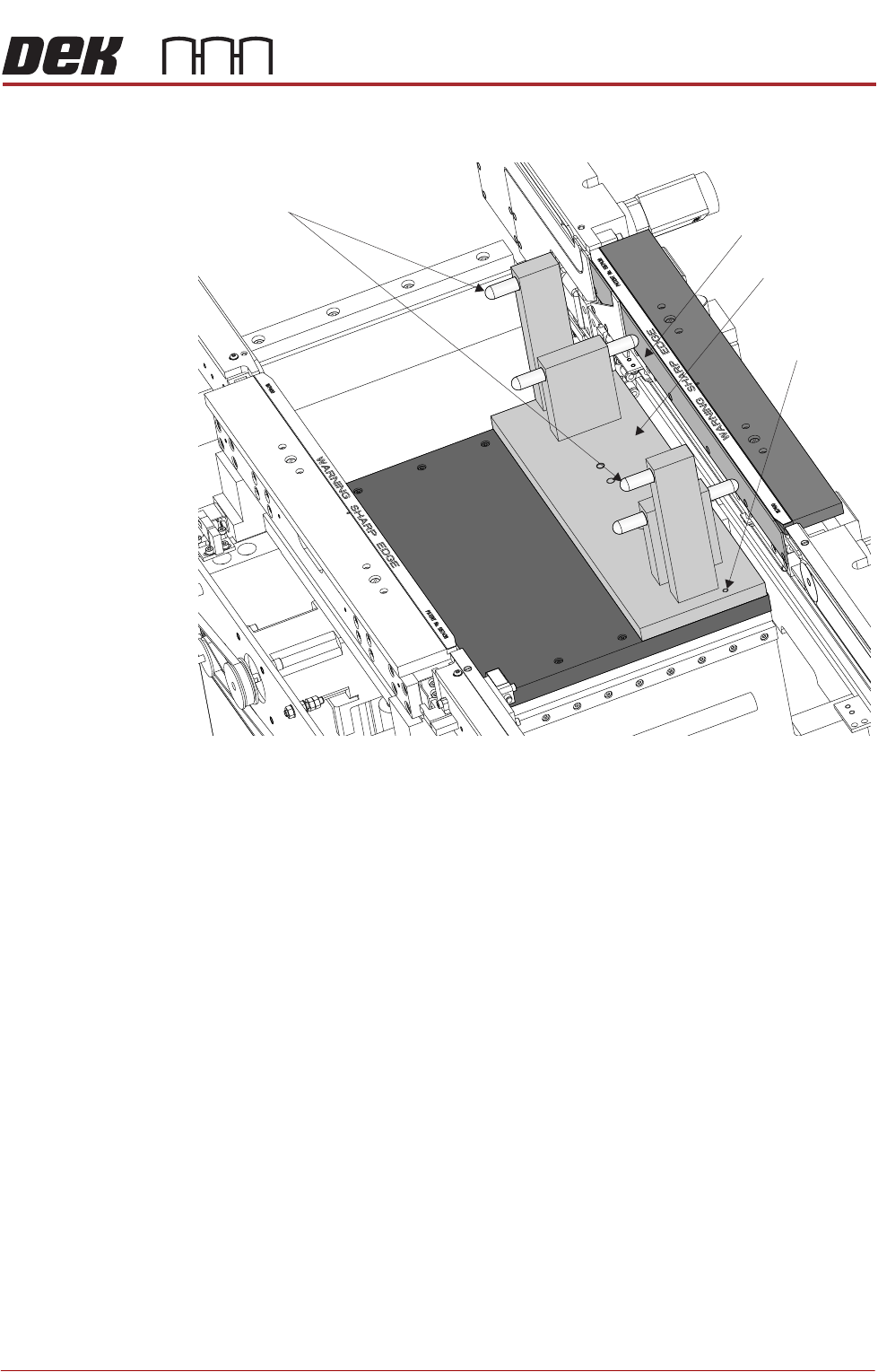
3. Fit the rail setting jig to the manual tooling plate locating the two dowels in
to the holes on the tooling plate.
NOTE
The rail setting jig must not exert any force on the front rail during placement.
If any force is felt, remove the jig and go to the Front Rail Parallelism section.
4. Manually pull the camera beam until the bearing guide on the camera beam
gently abuts the two camera beam stops on the rail setting jig.
5. Using a 0.05mm feeler as a NO-GO gauge, check that no gap exists
between the stops and the camera beam.
6. If adjustment is not required, manually move the camera beam away from
the jig and remove the jig from the rising table.
7. If adjustment is required, refer to the X Axis Parallelism - Adjustments and
Settings section in the Camera System Module chapter.
Board Support Plate
Rail Setting Jig
Locating Dowel
(in 2 positions)
Camera Beam Stops
RAPID TRANSIT CONVEYOR (RTC) MODULE
ADJUSTMENTS AND SETTINGS
22.16 Technical Reference Manual Chapter Issue 4, Aug 14
Rail to Table Height The rail to table height is factory set and must not be adjusted.
Board Clamp Setting
WARNING
BOARD CLAMPS. EXTREME CARE MUST BE EXERCISED WHEN WORKING IN
THE TOOLING AREA OF THE MACHINE TO AVOID INJURY. THE FOILS ON THE
FRONT AND REAR BOARD CLAMPS ARE VERY SHARP.
1. Raise the rising table to vision height.
2. Toggle the board clamps to On.
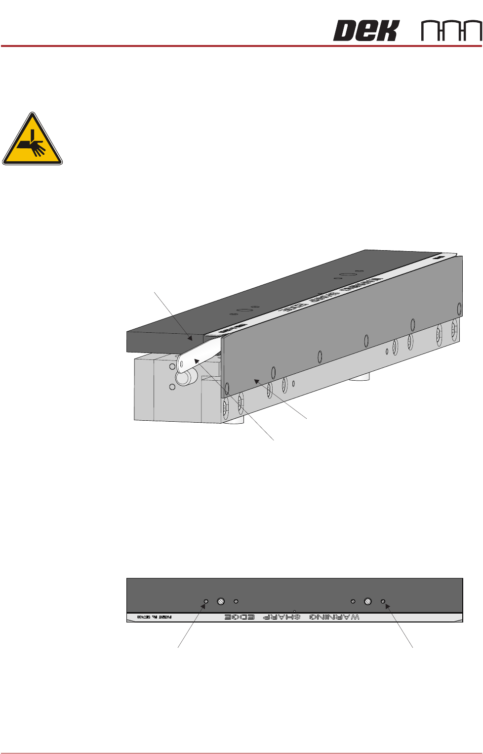
3. Using a 0.6mm feeler gauge, check that the gap between the board clamp
and the board support plate on both ends of the front print station rail.
4. Using a 0.6mm feeler gauge, check that the gap between the board clamp
and the board support plate on both ends of the rear print station rail.
5. If no adjustment is required, go to Step 10.
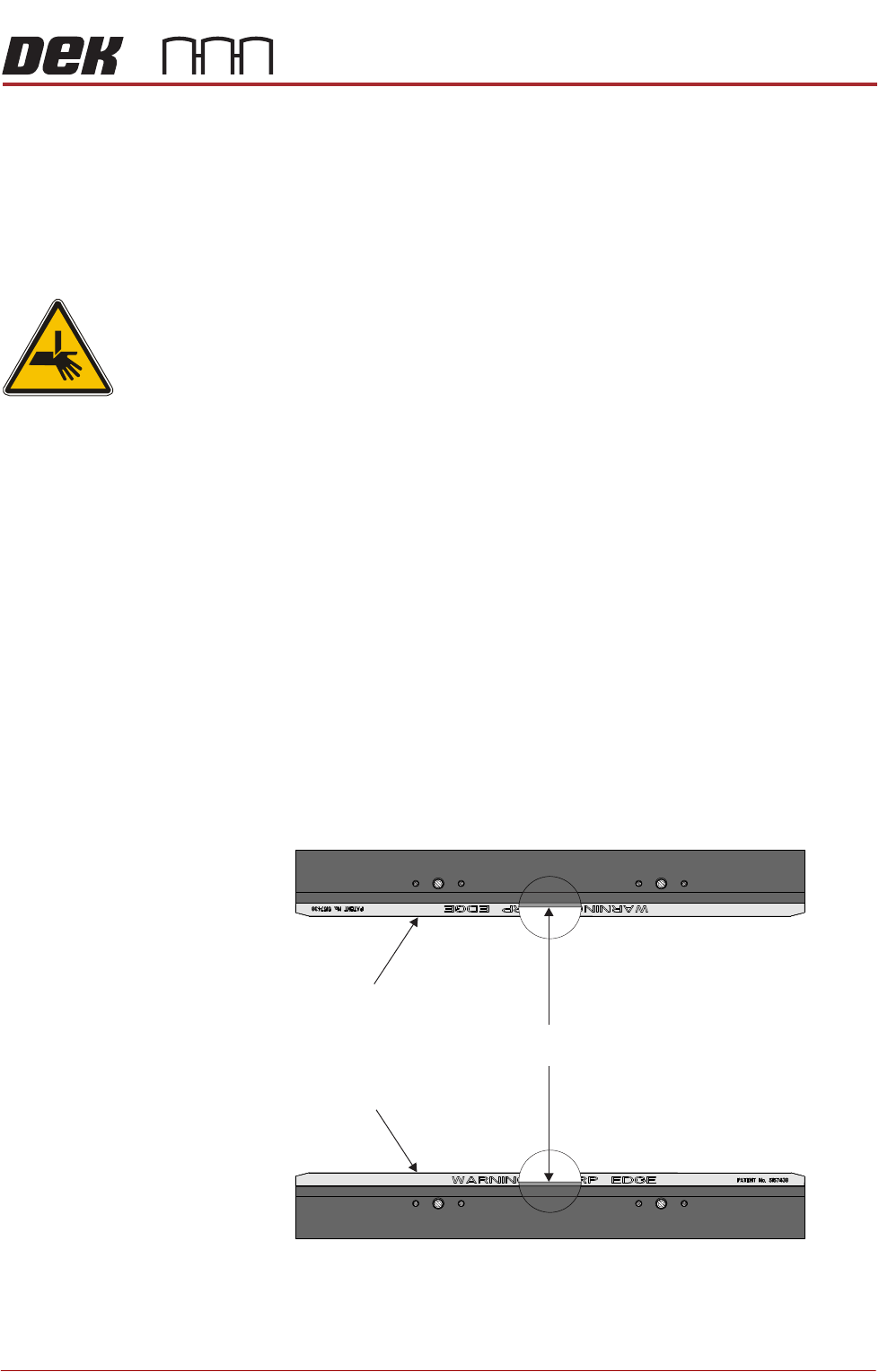
6. To adjust the board clamp setting, loosen the two board clamp adjustment
screws using a flat bladed screwdriver.
7. Using feeler gauges, move the board clamp to achieve the 0.6mm gap
between the board clamp and the board support plate on both ends of the
print station rail.
8. Tighten the two board clamp adjustment screws.
Board Support Plate
Feeler Gauge
Board Clamp
View on Inside of Print Station Rail
Plan View of Print Station Rail
Board Clamp
Adjustment Screw
Board Clamp
Adjustment Screw
RAPID TRANSIT CONVEYOR (RTC) MODULE
ADJUSTMENTS AND SETTINGS
Chapter Issue 4, Aug 14 Technical Reference Manual 22.17
9. Recheck the gap at both ends of the print station rail.
10. Remove the feeler gauges.
11. Toggle the board clamps to Off.
12. Home the rising table.
Home Position Rail Width Check
WARNING
BOARD CLAMPS. EXTREME CARE MUST BE EXERCISED WHEN WORKING IN
THE TOOLING AREA OF THE MACHINE TO AVOID INJURY. THE FOILS ON THE
FRONT AND REAR BOARD CLAMPS ARE VERY SHARP.
1. Ensure the board clamps are fitted and the Board Clamp Setting procedure
has been carried out.
2. In Diagnostics select Rapid Transit Conveyor module.
3. Select Home Rapid Transit Conveyor Inroad Vane Motor.
4. Select Home Rapid Transit Conveyor Board Transport Motor.
5. Select Home Rail Width.
6. Select Adjust and set board width to 250mm.
7. Select Exit.
8. Select Drive Rail to Board Width.
9. Select Run Diagnost.
10. Open the front printhead cover/shutter.
11. Place a vernier gauge just below the board clamp foil in the centre of the
board clamps and check that the vernier reads between 250.25mm
±0.10mm.
12. If the rail width is correct, go to Step 22.
13. Close the front printhead cover/shutter and press the System button when
Rear Board Clamp
Plan View of Board Clamps
250.25mm ±0.10mm
Front Board Clamp