192277 - Micron Technical Reference Volume 3 - 第43页
CAMERA SYSTE M MODULE OVERVIEW Chapter Issue 9, Feb 18 Technical Reference Manual 23.1 CHAPTER 23 CAMERA SYSTEM MODULE OVER VI EW Figure 23-1 Camera Overview Rota ry Drive Item Descrip tion Item Description 1 Camera Y Ho…
RAPID TRANSIT CONVEYOR (RTC) MODULE
CALIBRATIONS
22.30 Technical Reference Manual Chapter Issue 4, Aug 14
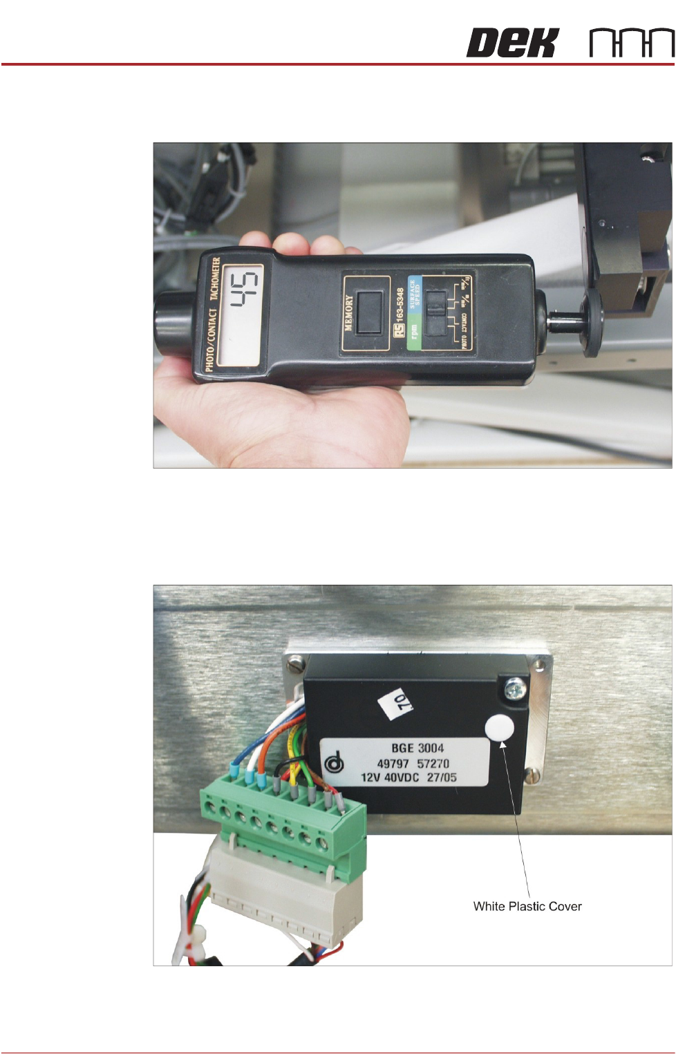
4. Using a tachometer fitted with the surface speed test wheel, positioned on
the input or output pulley, measure the speed of all four transport belts and
check that the speed is 44 - 46 metres/min.
5. If adjustment is required, using the labels attached to the cables connecting
to the motor speed controllers, identify which motor speed controller is
associated with the transport belt that needs to be adjusted.
6. Adjust the appropriate motor speed using the potentiometer situated
beneath the white plastic cover on the motor speed controller module.
7. Select Toggle Inroad Belts to stop the belts on the inroad conveyor.
8. Select Toggle Outroad Belts to stop the belts on the outroad conveyor.
9. Select Exit to leave diagnostics.
CAMERA SYSTEM MODULE
OVERVIEW
Chapter Issue 9, Feb 18 Technical Reference Manual 23.1
CHAPTER 23 CAMERA SYSTEM MODULE
OVERVIEW
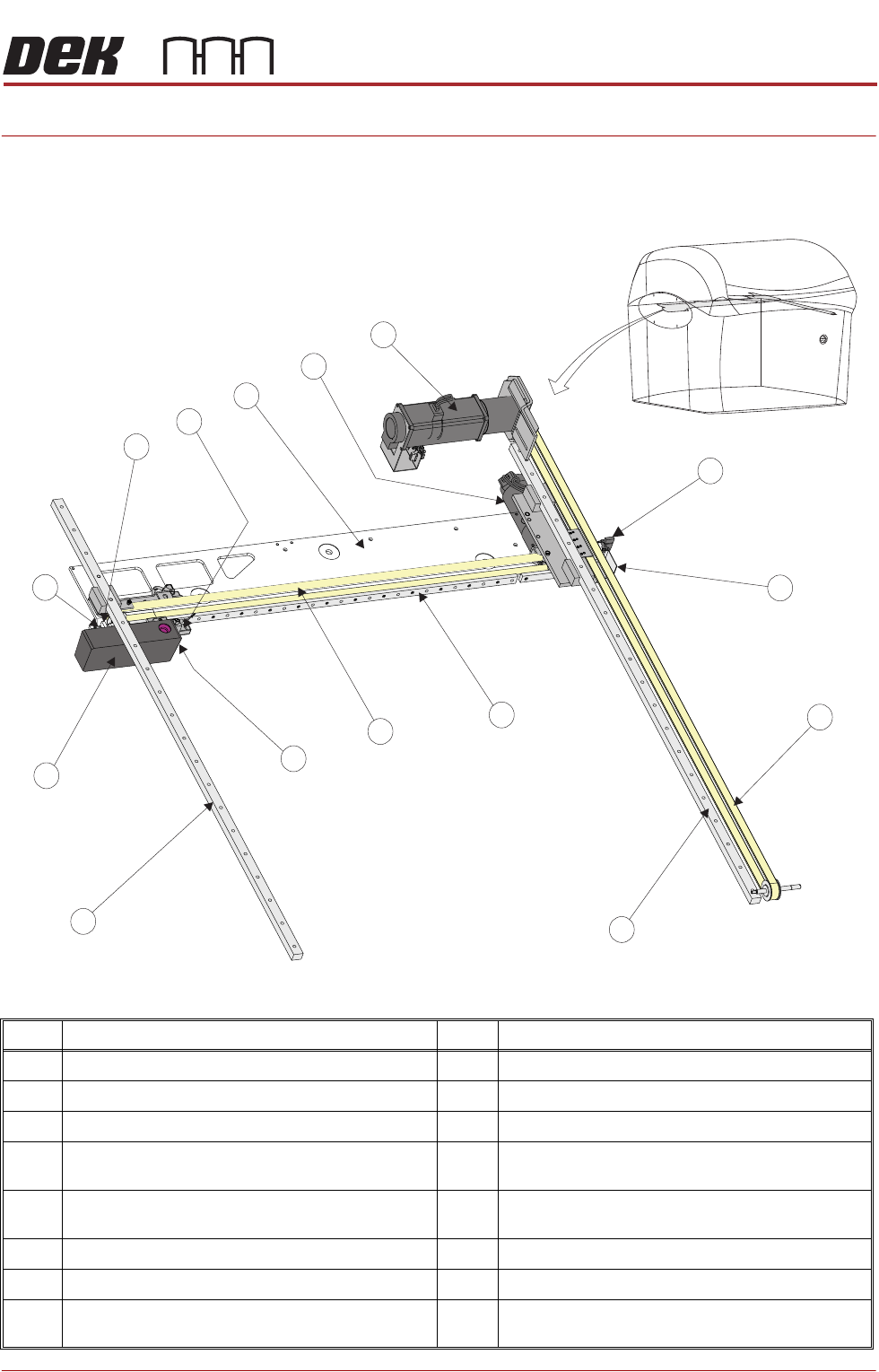
Figure 23-1 Camera Overview Rotary Drive
Item Description Item Description
1 Camera Y Home Sensor 9 Camera Assembly
2 Camera Y Home Vane 10 Camera X Home Vane
3 Y Axis Timing Belt 11 Camera X Home Sensor
4 Y Axis Right Hand Linear Bearing
(mounted on bottom of right hand printhead)
12 Camera Mounted Board Stop &
Board Stop Extended Sensor
5 X Axis Linear Bearing 13 Camera X Axis Support Platform
(shown transparent for clarity)
6 X Axis Timing Belt 14 Camera X Motor Node 8
7 Board at Stop Sensor 15 Camera Y Motor Node 9
8 Y Axis Left Hand Linear Bearing
(mounted on bottom of left hand printhead)
1
4
2
3
5
6
7
8
9
15
10
11
12
13
14
CAMERA SYSTEM MODULE
OVERVIEW
23.2 Technical Reference Manual Chapter Issue 9, Feb 18
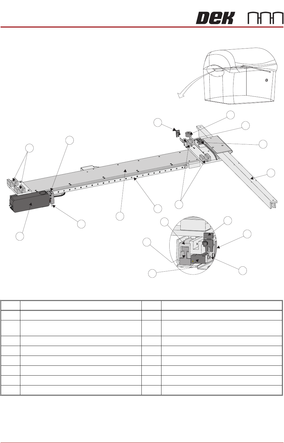
Figure 23-2 Camera Overview Linear Drive
NOTE
For Details on the Camera Mounted Board Stop and Board Stop Extended
Sensor see the Board Stop Chapter.
Item Description Item Description
1 Camera Y End Stop 9 Camera Assembly
2 Camera Y Home Vane 10 Camera Mounted Board Stop &
Board Stop Extended Sensor (See Note)
3 Camera Y Encoder 11 Camera Y Home Sensor
4 Camera Y Magnet Track 12 Camera X Home Vane
5 Linear Bearing (in 4 positions) 13 Camera X Encoder
6 Camera X Axis Linear Bearing 14 Camera X Forcer
7 Camera X Axis Support Platform 15 Camera X Magnet Track
8 Board at Stop Sensor 16 Camera X Home Sensor
1
4
2
5
7
8
9
10
11
3
5
6
13
12
14
9
View on End of Camera
15
16