192277 - Micron Technical Reference Volume 3 - 第44页
CAMERA SYSTEM MODULE OVERVIEW 23.2 Technical Reference Manual Chapter Issue 9, Feb 18 Figure 23-2 Camera Ove rview Linear Drive NOTE For Details on the Camera Moun ted Board Stop and Board Stop Extended Sensor see the Bo…
CAMERA SYSTEM MODULE
OVERVIEW
Chapter Issue 9, Feb 18 Technical Reference Manual 23.1
CHAPTER 23 CAMERA SYSTEM MODULE
OVERVIEW
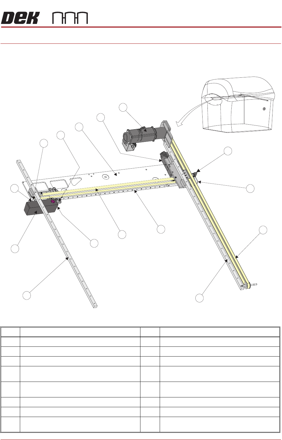
Figure 23-1 Camera Overview Rotary Drive
Item Description Item Description
1 Camera Y Home Sensor 9 Camera Assembly
2 Camera Y Home Vane 10 Camera X Home Vane
3 Y Axis Timing Belt 11 Camera X Home Sensor
4 Y Axis Right Hand Linear Bearing
(mounted on bottom of right hand printhead)
12 Camera Mounted Board Stop &
Board Stop Extended Sensor
5 X Axis Linear Bearing 13 Camera X Axis Support Platform
(shown transparent for clarity)
6 X Axis Timing Belt 14 Camera X Motor Node 8
7 Board at Stop Sensor 15 Camera Y Motor Node 9
8 Y Axis Left Hand Linear Bearing
(mounted on bottom of left hand printhead)
1
4
2
3
5
6
7
8
9
15
10
11
12
13
14
CAMERA SYSTEM MODULE
OVERVIEW
23.2 Technical Reference Manual Chapter Issue 9, Feb 18
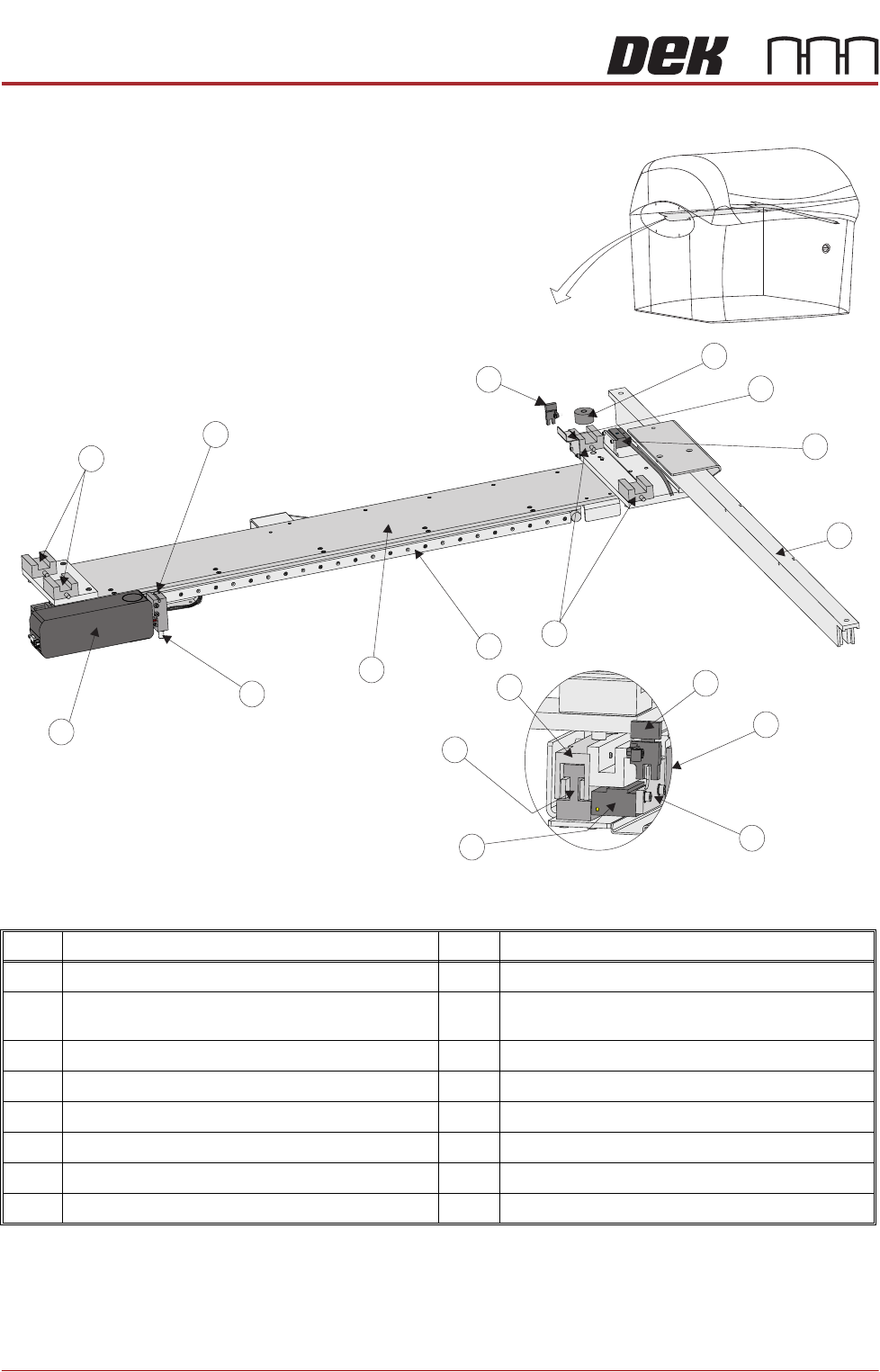
Figure 23-2 Camera Overview Linear Drive
NOTE
For Details on the Camera Mounted Board Stop and Board Stop Extended
Sensor see the Board Stop Chapter.
Item Description Item Description
1 Camera Y End Stop 9 Camera Assembly
2 Camera Y Home Vane 10 Camera Mounted Board Stop &
Board Stop Extended Sensor (See Note)
3 Camera Y Encoder 11 Camera Y Home Sensor
4 Camera Y Magnet Track 12 Camera X Home Vane
5 Linear Bearing (in 4 positions) 13 Camera X Encoder
6 Camera X Axis Linear Bearing 14 Camera X Forcer
7 Camera X Axis Support Platform 15 Camera X Magnet Track
8 Board at Stop Sensor 16 Camera X Home Sensor
1
4
2
5
7
8
9
10
11
3
5
6
13
12
14
9
View on End of Camera
15
16

CAMERA SYSTEM MODULE
OVERVIEW
Chapter Issue 9, Feb 18 Technical Reference Manual 23.3
The camera assembly traverses horizontally in the X and Y axis to position the
camera to carry out the following functions:
• Board Stop
• Fiducial Capture - for stencil to board alignment
• Site Capture - pre and post printing for 2Di inspection
• Moving the Underscreen Cleaner
Positioning of the camera assembly is carried out by the X and Y drive
mechanisms. There are two types of drive system, linear servo motor systems
and rotary servo motor systems.
The camera contains an optical unit for image focusing and a lighting unit for
board and stencil illumination during fiducial and 2D camera capture operations.
The camera carriage also contains the following:
• Camera Board Stop
• Board at Stop sensor
• Board Stop Extended Sensor
The camera board stop is a pneumatically driven unit which is lowered to stop
the board in position ready for clamping and vision alignment to take place.
The board at stop diffuse background suppressed opto detects the board when
it reaches the board stop. This starts a timer which when elapsed stops the belts
and clamps the board.
The board stop extended sensor is fitted to ensure that the board stop is raised
before any camera carriage movement is demanded.
The camera positions are referenced from the home position. Each camera axis
only homes during initialisation, which can be from power-up or exiting diagnos-
tics.
The camera system also provides the drive mechanism for the under screen
cleaner.
The camera system contains one of the following cameras:
• Hawkeye 750
• Hawkeye 1700