192277 - Micron Technical Reference Volume 3 - 第51页
CAMERA SYSTE M MODULE ADJUSTMENTS AND SETTINGS Chapter Issue 9, Feb 18 Technical Reference Manual 23.9 34. Bring the camera carriag e X axis support platform into conta ct with the camera alignment pins. 35. Look for a g…
CAMERA SYSTEM MODULE
ADJUSTMENTS AND SETTINGS
23.8 Technical Reference Manual Chapter Issue 9, Feb 18
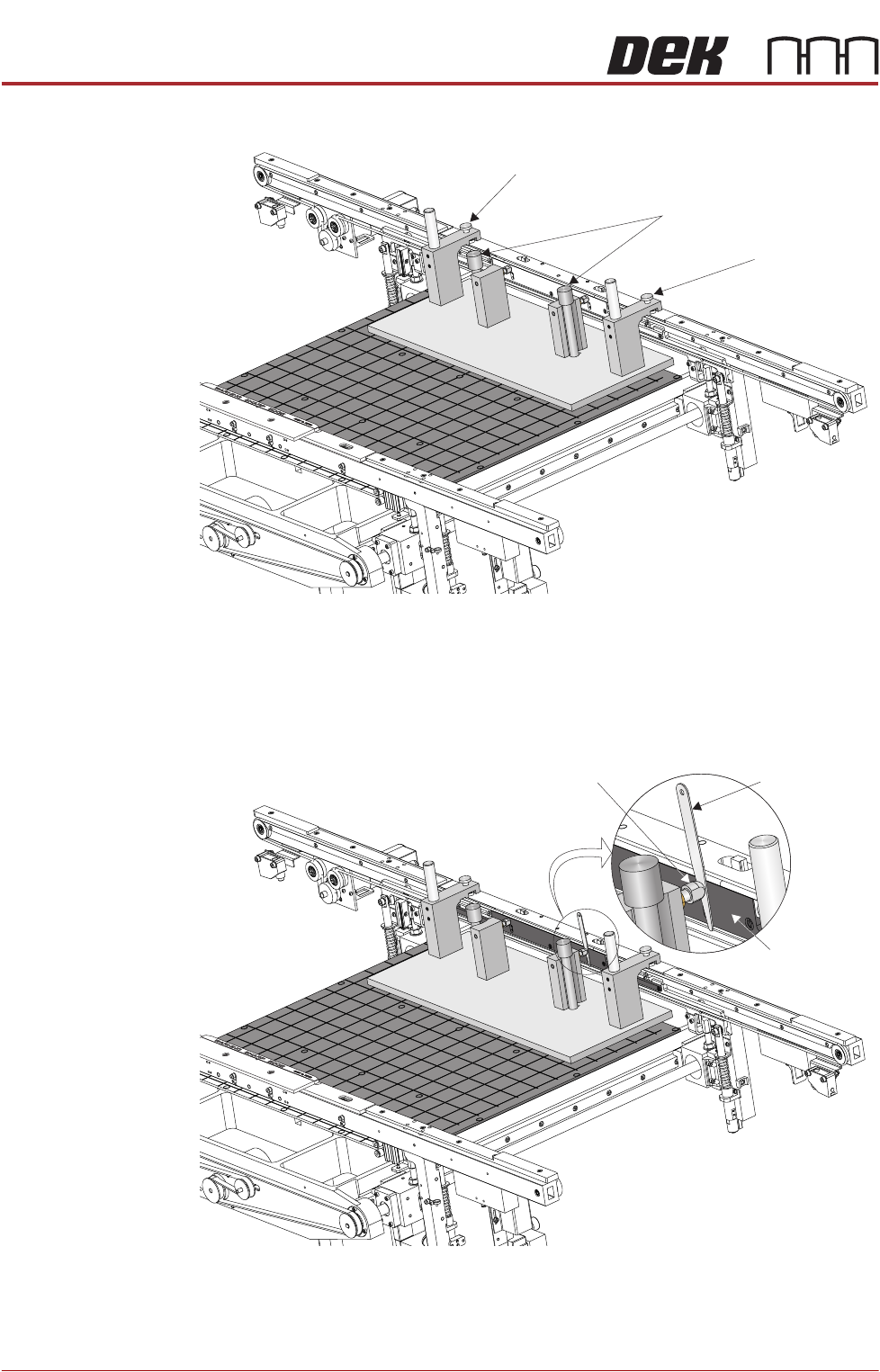
29. Secure the jig to the front rail using the two jig to rail thumbscrews.
30. Secure the jig to the rising table using the two jig to table thumbscrews.
31. Check that the location pins are up against the front edge of the manual
tooling plate using a 0.05mm feeler gauge, as in Step 28.
32. Using feeler gauges check that the gap between both alignment pads and
the belt support plate of the front rail is 0.25mm ±0.05mm.
33. If adjustment is necessary refer to the Transport Rails Module chapter -
Adjustments and Settings - Front Rail Parallelism.
View on Rear of Transport Rails
Jig to Table Thumbscrews
Jig to Rail Thumbscrew
Jig to Rail Thumbscrew
Feeler Gauge
Alignment
Pad
Belt Support
Plate
View on Rear of Transport Rails
CAMERA SYSTEM MODULE
ADJUSTMENTS AND SETTINGS
Chapter Issue 9, Feb 18 Technical Reference Manual 23.9
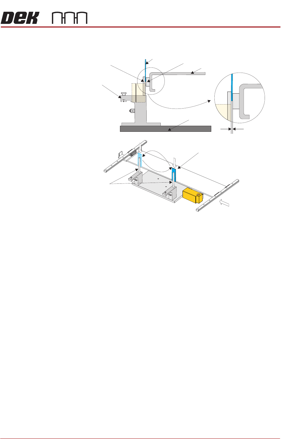
34. Bring the camera carriage X axis support platform into contact with the
camera alignment pins.
35. Look for a gap between the camera alignment pins and the linear bearing
on the front edge of the camera X axis support platform, if no gap exists
adjustment is unnecessary. Continue from Step 48.
36. If a gap exists, carefully attempt to insert a 0.25mm shim between the
alignment pin and the linear bearing on the front edge of the camera X axis
support platform. If the shim cannot be fitted the gap is less than 0.25mm
and adjustment is unnecessary. Continue from Step 48.
37. If a gap exists which is greater than 0.25mm adjustment is necessary.
38. For machines with rotary motors continue with Step 39. For machines with
linear motors go to Step 44.
View on Arrow A (Camera Y Axis Removed)
Camera Alignment
Pins (2 positions)
Alignment Jig
0.25 mm
Camera Parallelism Check
Camera Alignment
Pins (2 positions)
Shim 0.25 mm
A
Shim 0.25 mm
Camera X Axis Support Platform
Rising Table
Linear Bearing
CAMERA SYSTEM MODULE
ADJUSTMENTS AND SETTINGS
23.10 Technical Reference Manual Chapter Issue 9, Feb 18
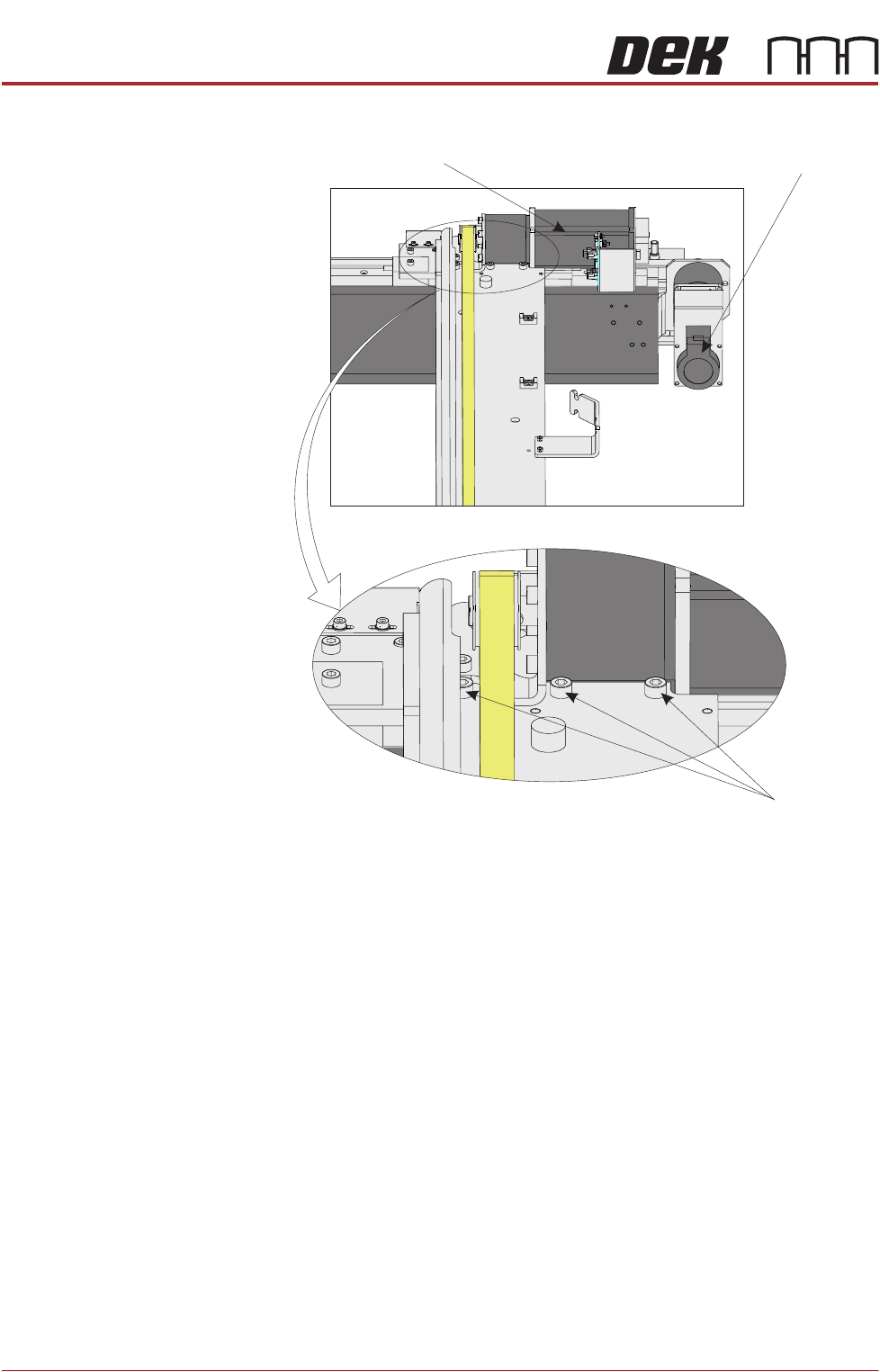
39. Loosen the three securing screws.
40. Using a soft headed mallet gently tap the edge of the camera X axis support
platform to close the gap on the camera alignment pins.
NOTE
The camera can be severely damaged if excessive force is used to position
the camera axis.
41. Tighten the three securing screws taking care not to allow the position to slip.
42. Check for parallelism again.
43. Go to Step 48.
Camera X Motor Camera Y Motor
View From Beneath Camera Carriage
Securing Screws