192277 - Micron Technical Reference Volume 3 - 第57页
CAMERA SYSTE M MODULE ADJUSTMENTS AND SETTINGS Chapter Issue 9, Feb 18 Technical Reference Manual 23.15 Vis ion Height for Standard and MTR Rail Syst ems W ARNING BOARD CLAMPS. EXTREME CA RE MUST BE EXERCIS ED WHEN WORKI…
CAMERA SYSTEM MODULE
ADJUSTMENTS AND SETTINGS
23.14 Technical Reference Manual Chapter Issue 9, Feb 18
air gap between the forcer and the magnet track is equal on both the left and
right side of the forcer.
28. Repeat Step 27 for the rear end of the magnet track.
29. If the alignment is correct, go to Step 33.
30. On the top surface of the Y Magnet Track locate the two magnet track
adjustment screws. Slacken the screws but do not remove. Gently move
the bracket in the direction required for the 0.5mm shim to fit comfortably all
around. Tighten the screws to secure.
31. Check the air gap again to ensure that the screws have been tightened
evenly without misaligning the forcer.
32. Slide the camera assembly along the whole length of the Y camera axis and
ensure there are no points where the forcer contacts the magnet track side
wall.
33. Refit the right side panel.
34. Refit the stencil.
35. Close the front printhead cover.
36. Power up the machine.
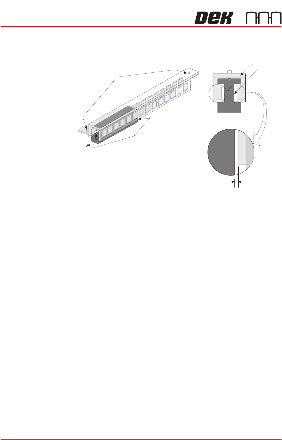
A
View on Arrow A
Forcer to Magnet Track
Air Gap (both sides)
0.5mm Min
Forcer
Magnet Track
Test both gaps, on
both ends of the
forcer
Y Forcer And Magnet Track
(Support brackets and fixings removed for clarity)
Magnet Track
Adjustment Screw (2)
CAMERA SYSTEM MODULE
ADJUSTMENTS AND SETTINGS
Chapter Issue 9, Feb 18 Technical Reference Manual 23.15
Vision Height for Standard and MTR Rail Systems
WARNING
BOARD CLAMPS. EXTREME CARE MUST BE EXERCISED WHEN WORKING IN
THE TOOLING AREA OF THE MACHINE TO AVOID INJURY. THE FOILS ON THE
FRONT AND REAR BOARD CLAMPS ARE VERY SHARP.
NOTE
Ensure the board file used has the correct board thickness value. Check rail /
camera X motor bracket clearance. Remember that the vision height may be
higher if a thinner board is used.
1. Select Unload Screen.
2. Open the front printhead cover.
3. Remove the stencil from the machine.
4. Place the board on the rails and slide to a central position.
5. Refit the stencil.
6. Close the front printhead cover.
7. Press the System button.
8. Select Load Screen.
9. Select Maintenance.
10. Select Diagnostics.
11. Use Next or Previous to highlight Rising Table.
12. Select Select Module.
13. Use Next or Previous to highlight Raise Table To Vision Height.
14. Select Run Diagnost.
15. Remove the left hand safety cover.
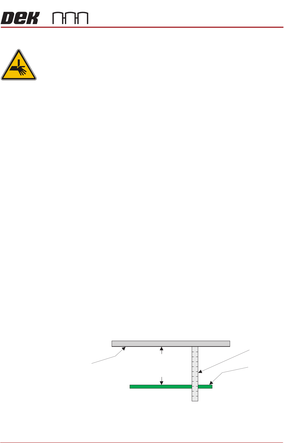
16. For exceptions, refer to the note below. Using a suitable metric rule,
measure the distance between the bottom of the stencil to the top of the
board. Check that the dimension is 78mm -0.0mm / +0.2mm, (ie the height
cannot be less than 78.0mm).
NOTE
For MTR and OTS transport rail systems, the vision height setting is set as
above, but the measurement is 79.5mm.
17. If the dimension is correct, go to Step 26.
18. Use Next or Previous to highlight Drive Table Using Jog Buttons.
19. Select Run Diagnost.
Top of Board
Metric Rule
Underside
of Stencil
Critical Dimension
78.0mm
(-0.0mm / +0.2mm)

CAMERA SYSTEM MODULE
ADJUSTMENTS AND SETTINGS
23.16 Technical Reference Manual Chapter Issue 9, Feb 18
20. Using jog buttons drive the rising table to achieve a vision height of 78mm
-0.0mm / +0.2mm, (ie the height cannot be less than 78.0mm)(For MTR
systems 79.5mm).
NOTE
a. The rising table must not be jogged up higher than the specified dimen-
sion, camera damage may occur.
b. The right jog button drives the rising table up, the left jog button drives the
rising table down.
21. Use Next or Previous to highlight Set Reference Vision Height.
22. Select Run Diagnost. The message ‘This Will Alter The Printer Config-
uration File - Please Confirm’ is displayed.
23. Select Confirm.
24. Use Next or Previous to highlight Home Rising Table.
25. Select Run Diagnost.
26. Refit the left hand safety cover.
27. Select Exit.
28. Select Exit.
29. Remove the board from the rails.
30. Select Back.
31. If the vision height has been adjusted a vision calibration and an offset
calibration must be carried out.
Camera Focus The camera focus is factory set and sealed and should not need adjustment.
Camera Reference Position
1. Select Maintenance.
2. Select Diagnostics.
3. Use Next or Previous to highlight Camera Axes.
4. Select Select Module.
5. Use Next or Previous to highlight Home Camera X Axis.
6. Select Run Diagnost.
7. Use Next or Previous to highlight Home Camera Y Axis.
8. Select Run Diagnost.
9. Use Next or Previous to highlight Initialise Vision System
.
10. Select Run Diagnost.
11. Select Drive to Reference Position.
12. Select Run Diagnost, a box and the white dot on the board clamp are visible