192277 - Micron Technical Reference Volume 3 - 第60页
CAMERA SYSTEM MODULE REPLACEMENT PROCEDURES 23.18 Technical Reference Manual Chapter Issue 9, Feb 18 REPLACEMENT PROCE DURES Camera W ARNING BOARD CLAMPS. EXTREME CA RE MUST BE EXERCIS ED WHEN WORKING IN THE TOOLING AREA…
CAMERA SYSTEM MODULE
ADJUSTMENTS AND SETTINGS
Chapter Issue 9, Feb 18 Technical Reference Manual 23.17
on the monitor.
13. If the reference position is correct, go to Step 18.
14. Using Move Camera X Axis Using Jog Buttons and Move Camera Y Axis
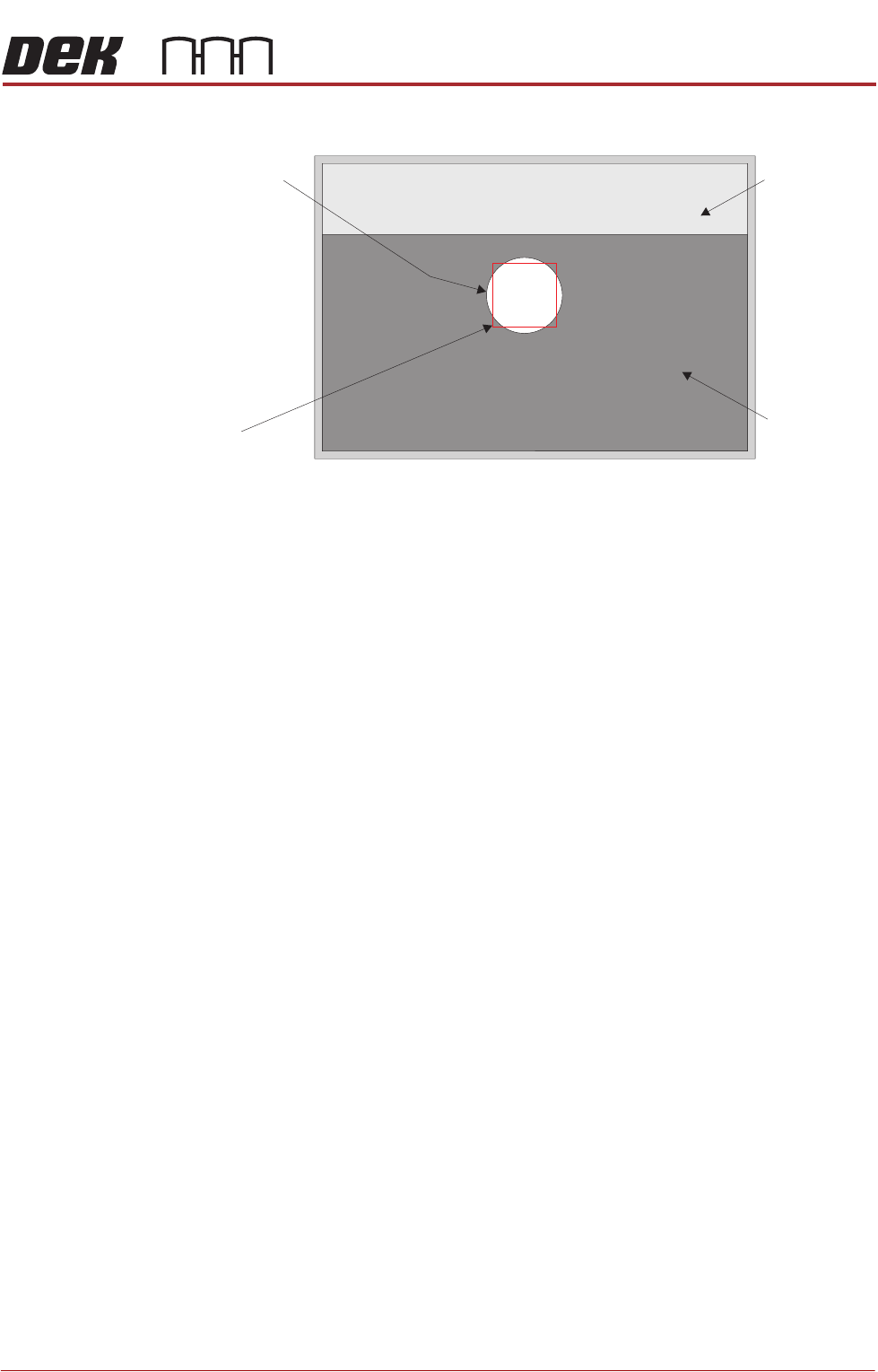
Using Jog Buttons, position the box centrally inside the white dot, as
shown in the graphic in Step 12.
15. Use Next or Previous to highlight Set Reference Position.
16. Select Run Diagnost. The message ‘This Will Alter The Printer Config-
uration File - Please Confirm’ is displayed.
17. Select Confirm.
18. Select Exit.
19. Select Exit.
20. Select Back.
Board Clamp
Foil
Board Clamp
Box
White Dot
CAMERA SYSTEM MODULE
REPLACEMENT PROCEDURES
23.18 Technical Reference Manual Chapter Issue 9, Feb 18
REPLACEMENT PROCEDURES
Camera
WARNING
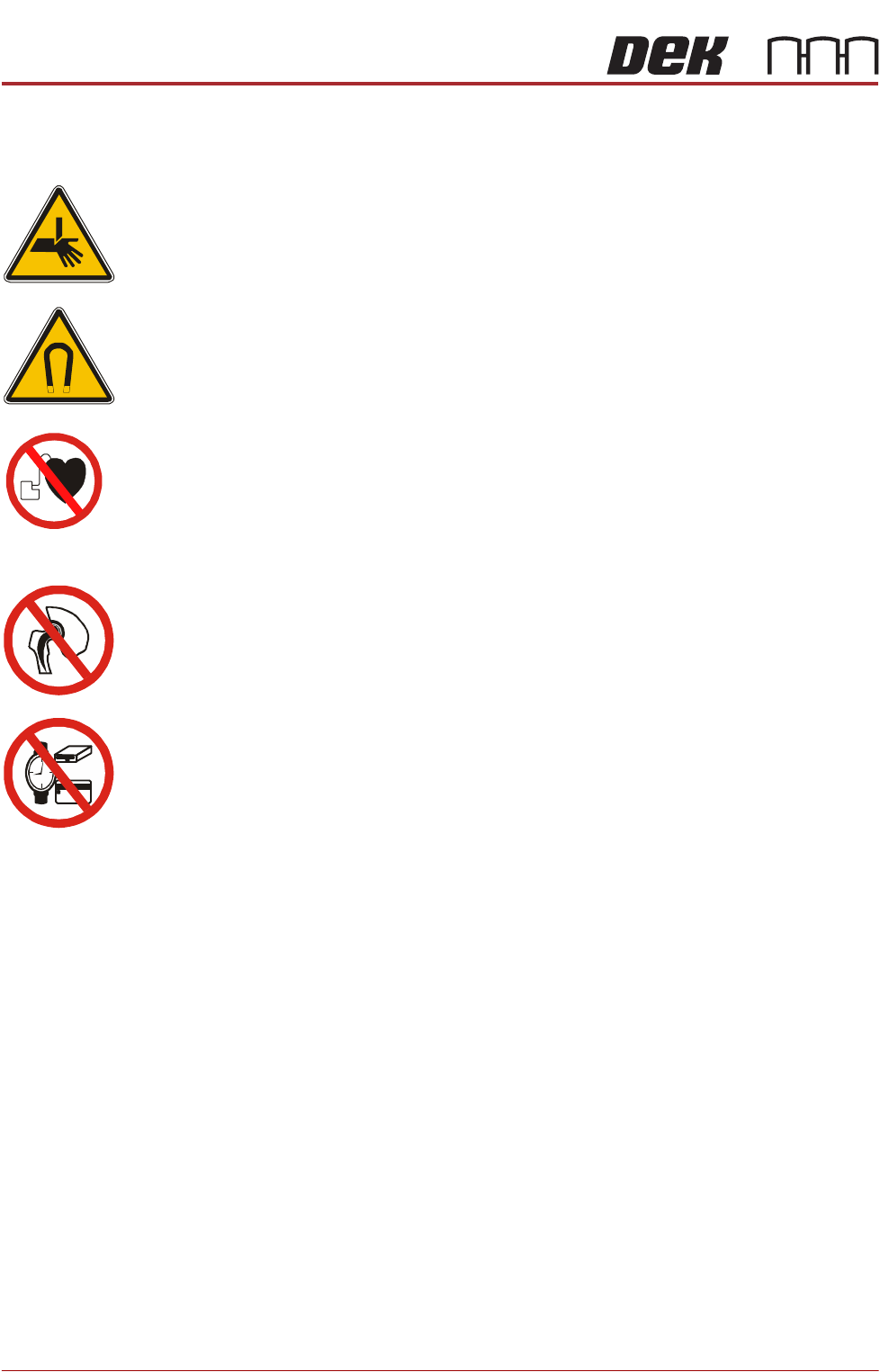
BOARD CLAMPS. EXTREME CARE MUST BE EXERCISED WHEN WORKING IN
THE TOOLING AREA OF THE MACHINE TO AVOID INJURY. THE FOILS ON THE
FRONT AND REAR BOARD CLAMPS ARE VERY SHARP.
WARNING
STRONG MAGNET FIELD. A STRONG MAGNETIC FIELD EXISTS IN THE
VICINITY OF THIS LABEL. THIS MAY PRESENT A HAZARD TO PERSONNEL OR
EQUIPMENT.
))
((
PROHIBITION
ELECTROMAGNETIC FIELD. AN ELECTROMAGNETIC FIELD EXISTS WITHIN
THE MACHINE FROM THE LINEAR MOTORS. THESE MAY PRESENT A HAZARD
TO PEOPLE FITTED WITH AN IMPLANTED CARDIAC DEVICE. THE MOTOR
MANUFACTURER RECOMMENDS A SAFE DISTANCE OF AT LEAST 15MM.
PROHIBITION
ELECTROMAGNETIC FIELD. AN ELECTROMAGNETIC FIELD EXISTS WITHIN
THE MACHINE FROM THE LINEAR MOTORS. THESE MAY PRESENT A HAZARD
TO PEOPLE FITTED WITH AN IMPLANTED CARDIAC DEVICE. THE MOTOR
MANUFACTURER RECOMMENDS A SAFE DISTANCE OF AT LEAST 15MM.
PROHIBITION
STRONG MAGNETIC FIELD. A STRONG MAGNETIC FIELD EXISTS IN THE
VICINITY OF THE LINEAR MOTORS THAT REPRESENT A SERIOUS HAZARD TO
PEOPLE FITTED WITH METALLIC IMPLANTS.
PROHIBITION
STRONG MAGNETIC FIELD. A STRONG MAGNETIC FIELD EXISTS IN THE
VICINITY OF THE LINEAR MOTORS THAT MAY ACT UPON FERROUS OBJECTS
WHOSE MOVEMENTS COULD LEAD TO PERSONAL INJURY AND/OR DAMAGE
TO THE MACHINE.
The following procedure is valid for all cameras.
Removal 1. Select Open Cover Commands.
2. Select Carriage To Rear.
3. Select Back.
4. Select Shut Down.
5. Select Continue.
6. Switch the mains isolator to OFF.
7. Open the front printhead cover.
8. Remove the stencil.
9. To gain access to the camera for removal, move the camera forward and
central over the table by manually moving the camera carriage.
10. Remove the following connectors from the rear of the camera unit:
•10SK17
•10SK13
CAMERA SYSTEM MODULE
REPLACEMENT PROCEDURES
Chapter Issue 9, Feb 18 Technical Reference Manual 23.19
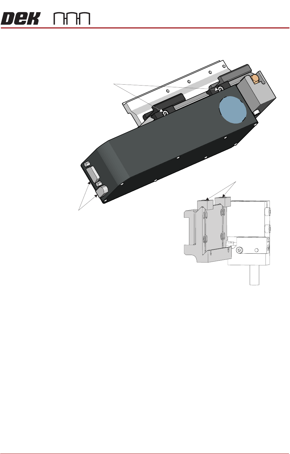
11. Loosen the two camera mount screws and lift the dovetail fixings to free the
camera, lift the camera out of the camera mount.
Fitment 12. Slide the camera into position in the dovetail ensuring that the end of the
camera mount butts against the right hand side of the dovetail and secure
camera mount screws (2).
13. Connect 10SK13 and 10SK17.
14. Ensure that the cable-ties are secure and the cables are positioned to
prevent any chaffing on the board clamps or transport rails.
15. Refit the stencil.
16. Close the front printhead cover.
17. Power up the machine.
18. The following adjustments/calibrations must be carried out:
• Camera Reference Position Adjustment
• Board Stop X Offset Check Calibration
• Vision Calibration
• Calibrate Offset Calibration
Camera Mount with Camera Removed
Dovetail Fixings Remain in Place
Camera
Securing Screws
Camera
Connectors