192277 - Micron Technical Reference Volume 3 - 第62页
CAMERA SYSTEM MODULE REPLACEMENT PROCEDURES 23.20 Technical Reference Manual Chapter Issue 9, Feb 18 Camera X Axis Timing Belt (Rotary Servo Motor Systems Only) W ARNING BOARD CLAMPS. EXTREME CA RE MUST BE EXERCIS ED WHE…
CAMERA SYSTEM MODULE
REPLACEMENT PROCEDURES
Chapter Issue 9, Feb 18 Technical Reference Manual 23.19
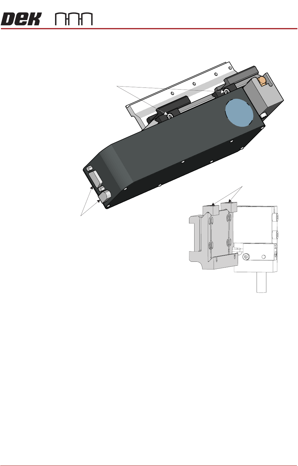
11. Loosen the two camera mount screws and lift the dovetail fixings to free the
camera, lift the camera out of the camera mount.
Fitment 12. Slide the camera into position in the dovetail ensuring that the end of the
camera mount butts against the right hand side of the dovetail and secure
camera mount screws (2).
13. Connect 10SK13 and 10SK17.
14. Ensure that the cable-ties are secure and the cables are positioned to
prevent any chaffing on the board clamps or transport rails.
15. Refit the stencil.
16. Close the front printhead cover.
17. Power up the machine.
18. The following adjustments/calibrations must be carried out:
• Camera Reference Position Adjustment
• Board Stop X Offset Check Calibration
• Vision Calibration
• Calibrate Offset Calibration
Camera Mount with Camera Removed
Dovetail Fixings Remain in Place
Camera
Securing Screws
Camera
Connectors
CAMERA SYSTEM MODULE
REPLACEMENT PROCEDURES
23.20 Technical Reference Manual Chapter Issue 9, Feb 18
Camera X Axis Timing Belt (Rotary Servo Motor Systems Only)
WARNING
BOARD CLAMPS. EXTREME CARE MUST BE EXERCISED WHEN WORKING IN
THE TOOLING AREA OF THE MACHINE TO AVOID INJURY. THE FOILS ON THE
FRONT AND REAR BOARD CLAMPS ARE VERY SHARP.
1. Select Maintenance.
2. Select Diagnostics.
3. Select Exit.
NOTE
Exiting diagnostics initialises the machine, homing the camera axes.
4. Select Back.
5. Select Shut Down.
6. Select Continue.
7. Switch the mains isolator to OFF.
8. Open the front printhead cover.
9. Remove the stencil from the machine.
10. Remove the left and right side panels.
11. Slacken the idle pulley locknut at the left hand end of the camera carriage.
12. Slide the pulley inwards to release tension on the timing belt.
13. Slacken the four timing belt clamp securing screws sufficiently to remove the
timing belt from the clamp.
NOTE
Take note of the routing of the timing belt before removing it.
14. Remove the timing belt and discard.
15. Route the replacement timing belt around the camera X motor pulley and
the idle pulley.
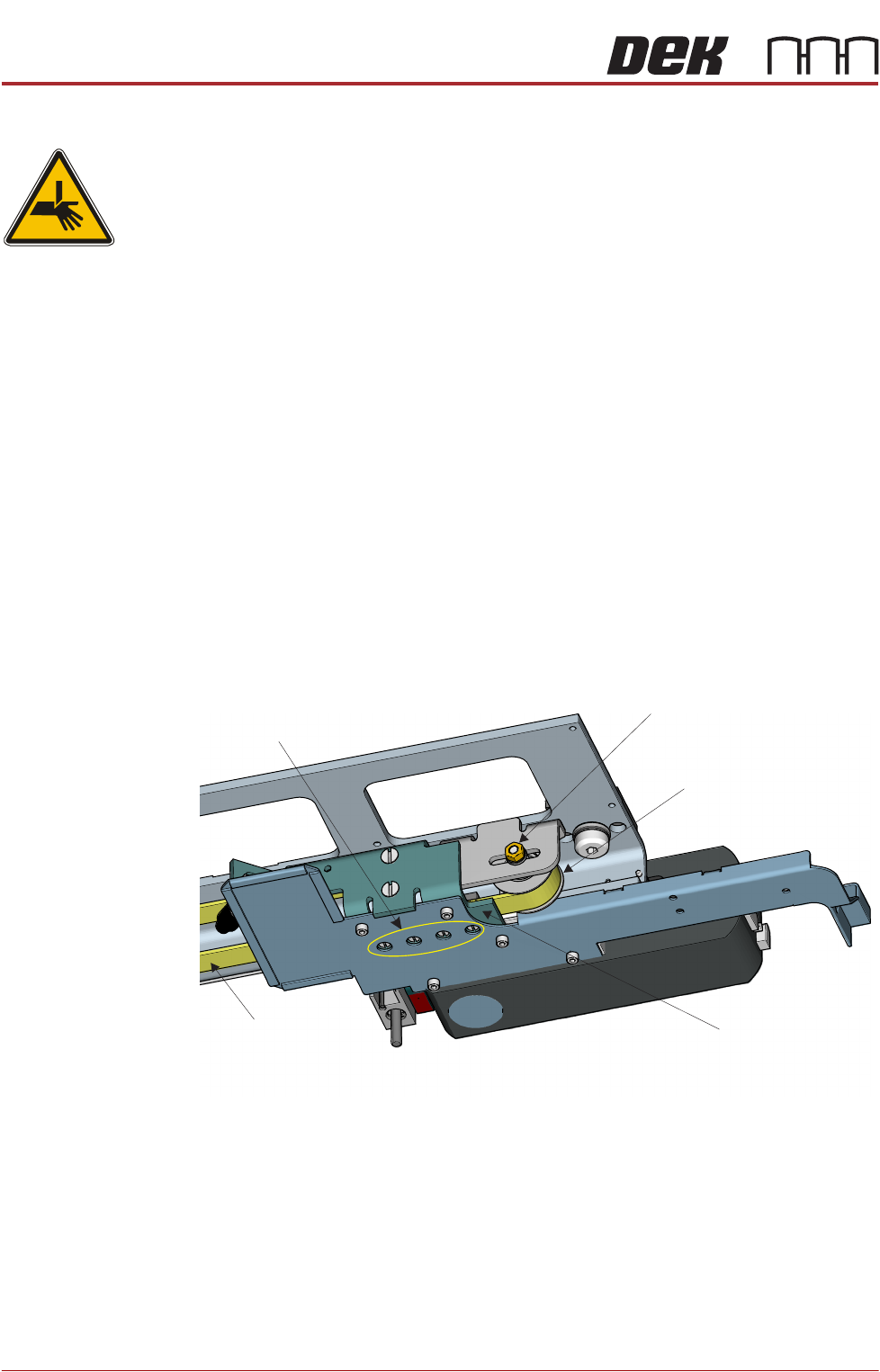
View From Beneath Camera Carriage
Idle Pulley
Securing Screws
(in 4 positions)
Locknut
Timing Belt
Timing Belt Clamp
CAMERA SYSTEM MODULE
REPLACEMENT PROCEDURES
Chapter Issue 9, Feb 18 Technical Reference Manual 23.21
16. Engage the two ends of the replacement timing belt equally into the timing
belt clamp. Tighten the timing belt clamp screws sufficiently to allow belt
movement. Ensure the timing belt is straight between the two pulleys and
the timing belt clamp.
17. Fully tighten the timing belt clamp screws.
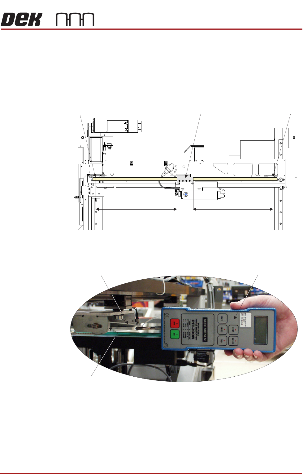
18. Manually position the timing belt clamp on the camera X axis timing belt so
that the distance X1 is equal to the distance X2.
19. Using a suitable cable tie, engage a forcemeter across the idle pulley. Apply
a horizontal force of 24kg to the belt. Maintaining this force, tighten the
locknut.
20. Remove the forcemeter. Do not remove the cable tie as further adjustment
may be necessary.
View on Underneath of Camera X Axis Support Platform
Timing Belt Clamp Idle Pulley (LHS)Camera X Motor Pulley (RHS)
X1 X2
View on Left Hand Side of Machine
Forcemeter
Cable Tie
Idle Pulley
24.0 kg