192277 - Micron Technical Reference Volume 3 - 第72页
CAMERA SYSTEM MODULE CALIBRATIONS AND CHECKS 23.30 Technical Reference Manual Chapter Issue 9, Feb 18 Vision Syste m Calibration For the vision alignment to function accurately a full system ca libration is required. Thi…
CAMERA SYSTEM MODULE
CALIBRATIONS AND CHECKS
Chapter Issue 9, Feb 18 Technical Reference Manual 23.29
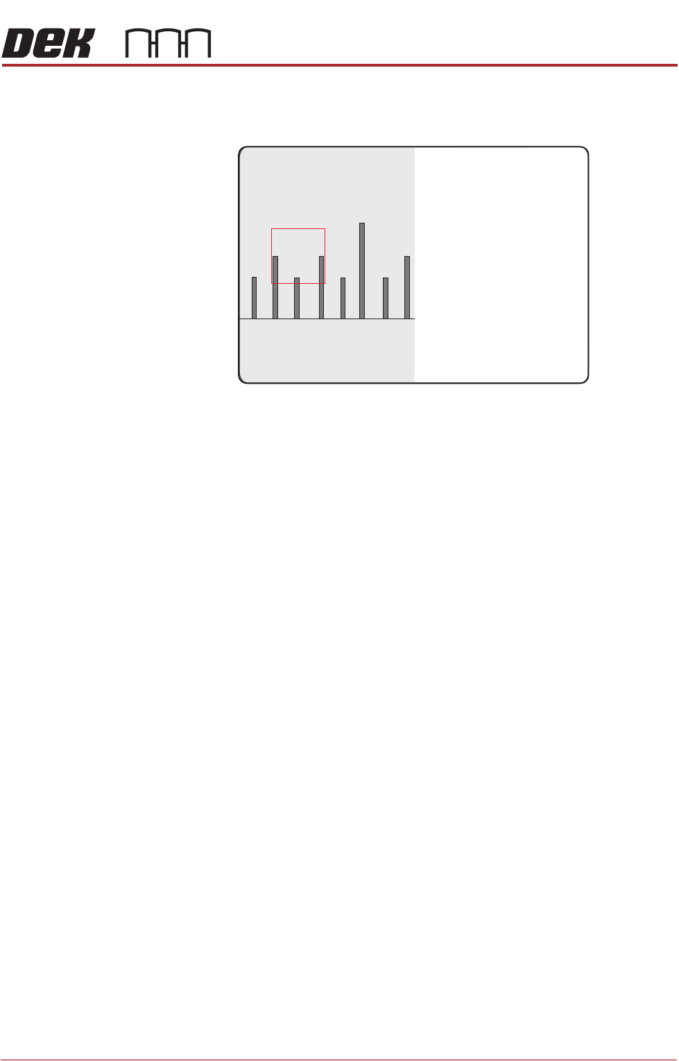
40. On the vision monitor, record the distance from the board edge to the
approximate centre of the square (figure below refers). This value is the
Board Stop X Offset and should be -43.5mm ±0.5mm.
NOTE
The numerals on the rule may not be directly in the field of view, move the
rule until the numerals are visible in the vision window. Lay the rule flat on
the board, do not lift or angle it as this can distort the measurement. As the
board stop is before the camera the distance is recorded as a minus reading.
41. Remove the rule from the machine.
42. Close the front printhead cover.
43. Press the System button.
44. Select Exit.
45. During Initialisation, remove the board from the transport rails when
prompted.
46. Select Continue.
47. Select Back.
48. Select Maintenance.
49. Select Machine Setup.
50. Select Basics.
51. Select Board Stop X Offset.
52. Enter the dimension obtained in Step 40.
53. Select Accept.
54. Select Back.
55. Select Back.
56. Select Back.
45
43 4644

CAMERA SYSTEM MODULE
CALIBRATIONS AND CHECKS
23.30 Technical Reference Manual Chapter Issue 9, Feb 18
Vision System
Calibration
For the vision alignment to function accurately a full system calibration is
required. This should be carried out by the maintenance personnel at the
required period.
The calibration of the vision system is carried out in two stages using a
calibration stencil (Part No. 134764) and a calibration board (Part No. 134765).
NOTE
1. For RTC and Dual Lane machines, the calibration is carried out using;
CALIBRAsmall product file, small calibration stencil (Part No. 431050) and
small calibration board (Part No. 187128).
2. On a Dual Lane front print machine, rail 3 may need to be moved to
accommodate a rail width of 254mm for the CALIBRAsmall board.
The first stage, Calibrate Vision, details the calibration of X, Y and Theta.
Calibrate Video X, Y calculates the stencil movement in millimetres to vision
system pixels. This is achieved by looking up at the calibration stencil fiducials
and moving the stencil in the X and Y directions by a fixed amount, for each of
the 25 fiducials.
The movements are calculated for each fiducial and the mean taken. This
average stencil movement is recorded and used as part of the calibration data.
Calibrate Theta calibrates the stencil theta movement. The camera selects
three stencil fiducials and the stencil moves in theta (using the two X axes and
implementing +2mm in X rear and -2mm in X forward to achieve the theta
movement). The movements are calculated for each fiducial and the average
taken. The data is recorded and the calibration is complete.
The second stage, Calibrate Offset is to compensate for any optical discrepan-
cies of the telecentric camera between viewing up and down. This is achieved
by printing the calibration stencil and measuring the differences between the
centroid of the stencil fiducials and the centroid of the printed fiducials. The
average of these differences are calculated, recorded and used as part of the
calibration data.
Calibration
Procedure
NOTE
The vision height adjustment must be carried out prior to calibrating the vision
system
The calibration sequence is as follows:
• Stage 1 - Calibrate Vision
• Stage 2 - Calibrate Offset
Stage 1 - Calibrate
Vision
NOTE
ASM recommends that the calibration board and stencil are cleaned with
Isopropyl Alcohol (IPA) impregnated lint free wipe prior to calibrating vision or
offset.
1. Select Maintenance.
2. Select Machine Setup.
3. Ensure that the Stencil Size parameter is set to 265.
4. Select Back.

CAMERA SYSTEM MODULE
CALIBRATIONS AND CHECKS
Chapter Issue 9, Feb 18 Technical Reference Manual 23.31
5. Select Back.
6. Select Setup Product.
7. Select Load Product.
8. Select Calibra.
9. Select Load.
10. Select Back.
11. Select Back.
12. Select Unload Screen.
13. Open the front printhead cover.
14. Remove the stencil and fit the calibration stencil.
15. Close the front printhead cover.
16. Press the System button.
17. Select Setup Product.
18. Select Fiducials.
19. Select Global Settings.
20. Ensure that Alignment Mode is set to 2 Fiducial.
21. Select Back.
22. Select Back.
23. Select Back.
24. Select Maintenance.
25. Select Calibrations.
26. Select Vision.
27. Select Screen OK.
28. Select Use Screen, if displayed.
29. Load the calibration board on to the input conveyor.
30. Select Auto Board, the board moves to the board stop position.
31. Select Step, the board is clamped and the board stop retracts.
32. Select Step, the camera moves to the first stencil fiducial and the squeegee
moves to dwell height.
33. Using the Incr. and Decr. buttons and viewing the right hand side of the
vision monitor, position the stencil fiducial so that it is placed centrally with
the box displayed.
34. Select Step, the camera moves to the second stencil fiducial. Position the
fiducial centrally with the box as previously described.
35. Select Step, the camera moves to the third stencil fiducial. Position the
fiducial centrally with the box as previously described.
36. Select Step, the camera moves to the fourth stencil fiducial. Position the
fiducial centrally with the box as previously described.
37. Select Step.
The control screen displays the following message, ‘Printer configuration