192277 - Micron Technical Reference Volume 3 - 第78页
CAMERA SYSTEM MODULE APPENDIX A - VISION SYSTEM SET UP 23.36 Technical Reference Manual Chapter Issue 9, Feb 18 APPENDIX A - VISION SYSTEM SET UP Preparing the Vision Syste m The following procedure is typical for all fi…
CAMERA SYSTEM MODULE
CALIBRATIONS AND CHECKS
Chapter Issue 9, Feb 18 Technical Reference Manual 23.35
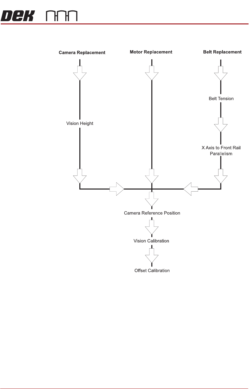
Associated Calibrations
Figure 23-5 Associated Calibrations
NOTE
For information on the Test Cycles function see the Stencil Alignment Chapter.
CAMERA SYSTEM MODULE
APPENDIX A - VISION SYSTEM SET UP
23.36 Technical Reference Manual Chapter Issue 9, Feb 18
APPENDIX A - VISION SYSTEM SET UP
Preparing the
Vision System
The following procedure is typical for all fiducial shapes, although in this
procedure a circle fiducial shape is referred to throughout.
1. Select Setup Product.
2. Select Fiducials.
3. Select Load Board.
4. Place a board on the input side of the rails.
5. Select Auto Board.
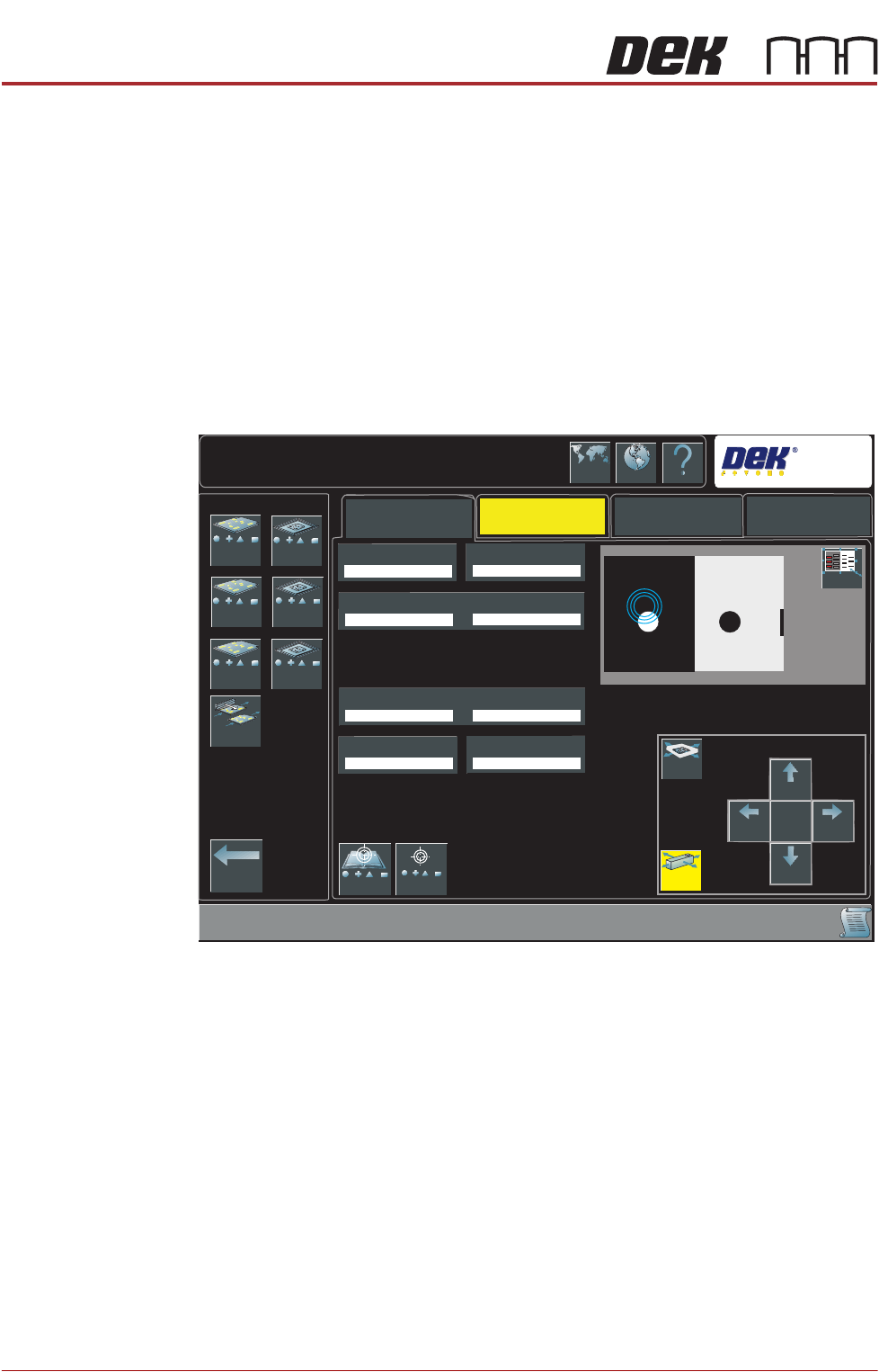
6. Select Fiducial Setup.
7. The following window is displayed:
8. Select the board or stencil fiducial that requires setting up.
Auto Setup
Manual Setup
Setup\Fiducials\Fiducial Setup
Lighting
Search
DEK
1
2
3
1
2
3
Shape
Width
Board Fiducial 1X
Board Fiducial 1Y
Accept Score
Background
Contours Inner
Contours Outer
Fiducials -
Board 1
Fiducials -
Board 2
Selective Print
Pass Through
Learn and
Locate
Move
Graphic
Move
Camera
Large
View
Camera
Up
Camera
Down
Move
Amount
X1
Camera
Right
Camera
Left
Locate
Language
Interactiv Help
Exit
Fiducials -
Board 3
Fiducials -
Screen 1
Fiducials -
Screen 2
Fiducials -
Screen 3

CAMERA SYSTEM MODULE
APPENDIX A - VISION SYSTEM SET UP
Chapter Issue 9, Feb 18 Technical Reference Manual 23.37
9. Select Shape to change the fiducial type. The options are:
•Circle
• Rectangle
• Diamond
• Triangle
• Double Square
•Cross
• Video Model
NOTE
Video Model allows a unique feature to be used instead of a standard fiducial
shape.
10. Select Width to change the overall width of the fiducial.
11. Select Board/Screen Fiducial # X to change the location of the fiducial in
the X direction. The dimension is measured from the left hand side edge of
the board to the centre of the fiducial.
12. Select Board/Screen Fiducial # Y to change the location of the fiducial in
the Y direction. The dimension is measured from the front edge of the board
to the centre of the fiducial.
13. Select Contours Inner to setup the area within the fiducial to be ignored by
the vision system.
14. Select Contours Outer to setup the area outside the fiducial to be ignored
by the vision system.
15. Select Accept Score to setup the level as to whether a found fiducial should
be accepted or rejected.
16. Select Background to select whether the area surrounding the fiducial is
lighter or darker in comparison to the fiducial colour.
17. Select the Lighting tab.
18. Adjust the lighting parameters to a level whereby the fiducials just ‘white out’,
without blooming. Default level 8 on both Vertical and Oblique is usually
adequate for the majority of fiducials.
19. Select the Manual Setup tab.
20. If any changes have been made, go to Step 21. If no changes have been
made, go to Step 23.
21. Select Learn and Locate.
A figure appears on the monitor indicating the score of the fit between the
synthetic fiducial and the actual fiducial. The synthetic fiducial parameters
may need resetting and re-learning to obtain a better figure if there are other
features in the camera window.
22. Select Continue.
23. Select Locate.
24. Repeat Steps 8 to 20 for other fiducials that require setting up.
25. Select Exit.