192277 - Micron Technical Reference Volume 3 - 第80页
CAMERA SYSTEM MODULE APPENDIX A - VISION SYSTEM SET UP 23.38 Technical Reference Manual Chapter Issue 9, Feb 18 26. Select Unload Board . 27. Select Auto Board . 28. Select Back . 29. If the changes are permanent and nee…

CAMERA SYSTEM MODULE
APPENDIX A - VISION SYSTEM SET UP
Chapter Issue 9, Feb 18 Technical Reference Manual 23.37
9. Select Shape to change the fiducial type. The options are:
•Circle
• Rectangle
• Diamond
• Triangle
• Double Square
•Cross
• Video Model
NOTE
Video Model allows a unique feature to be used instead of a standard fiducial
shape.
10. Select Width to change the overall width of the fiducial.
11. Select Board/Screen Fiducial # X to change the location of the fiducial in
the X direction. The dimension is measured from the left hand side edge of
the board to the centre of the fiducial.
12. Select Board/Screen Fiducial # Y to change the location of the fiducial in
the Y direction. The dimension is measured from the front edge of the board
to the centre of the fiducial.
13. Select Contours Inner to setup the area within the fiducial to be ignored by
the vision system.
14. Select Contours Outer to setup the area outside the fiducial to be ignored
by the vision system.
15. Select Accept Score to setup the level as to whether a found fiducial should
be accepted or rejected.
16. Select Background to select whether the area surrounding the fiducial is
lighter or darker in comparison to the fiducial colour.
17. Select the Lighting tab.
18. Adjust the lighting parameters to a level whereby the fiducials just ‘white out’,
without blooming. Default level 8 on both Vertical and Oblique is usually
adequate for the majority of fiducials.
19. Select the Manual Setup tab.
20. If any changes have been made, go to Step 21. If no changes have been
made, go to Step 23.
21. Select Learn and Locate.
A figure appears on the monitor indicating the score of the fit between the
synthetic fiducial and the actual fiducial. The synthetic fiducial parameters
may need resetting and re-learning to obtain a better figure if there are other
features in the camera window.
22. Select Continue.
23. Select Locate.
24. Repeat Steps 8 to 20 for other fiducials that require setting up.
25. Select Exit.
CAMERA SYSTEM MODULE
APPENDIX A - VISION SYSTEM SET UP
23.38 Technical Reference Manual Chapter Issue 9, Feb 18
26. Select Unload Board.
27. Select Auto Board.
28. Select Back.
29. If the changes are permanent and need to be saved in the product file, go
to Step 30. If the changes are temporary, go to Step 31.
NOTE
If the changes are not saved, the changes remain in memory until the
machine is shut down or another product file is loaded.
30. Select Save.
31. Select Back.
32. Remove the board from the rails.
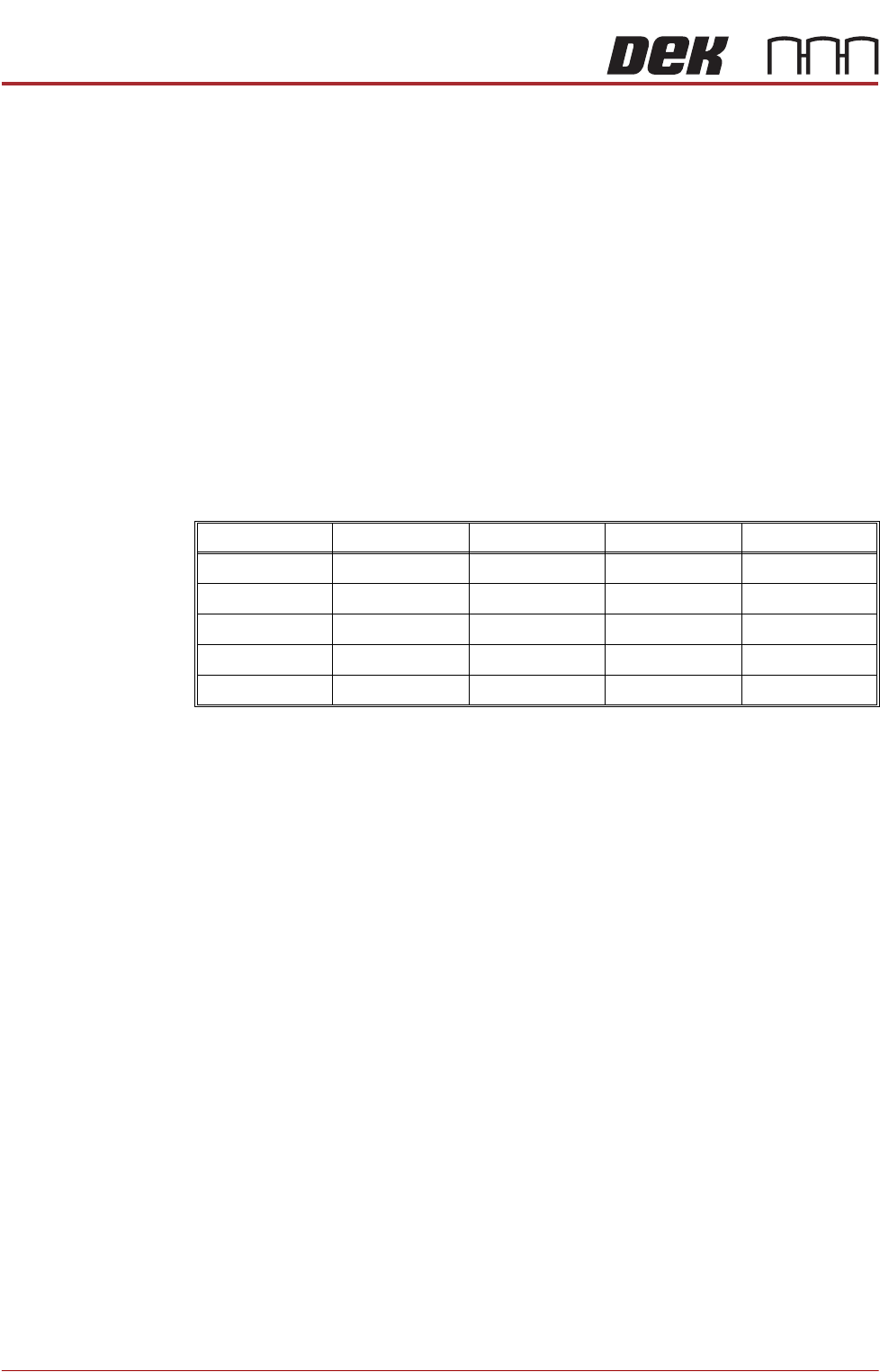
The above procedure is for a circular fiducial. There are some extra parameters
for the other fiducials which are listed in the table below:
Video Model If a board has no fiducials or the condition of the fiducials prevents satisfactory
recognition, the user can employ video models as an alternative to fiducials.
Video models use the relationship between the image of an area of the stencil
and the same area of the board to align the board and stencil. The area of the
board selected for use as a video model should have shapes with consistent,
solid boundaries. The shape should also have edges in both the X and Y planes
to produce an image with good X and Y information for accurate positioning.
There are three video model types:
• Auto - Uses a video model type best suited to the type of fiducial being
learnt.
• Type 1 - Uses a geometric pattern matching technique to produce a
synthetic model of the feature to be learnt. Best suited to features that are
not replicated in the camera field of view. A unique view is ideal for this
model.
• Type 2 - Uses a reference image to make a template of all the features and
the board background within the camera field of view and uses comparison
techniques to locate the model. A good choice where there is duplication
in the image such as a BGA device or QFP pad.
Rounding Height Rotation Leg Width
Rectangle Yes Yes Yes No
Diamond No Yes Yes No
Triangle No Yes Yes No
Double Square No Yes Yes No
Cross No Yes Yes Yes
BLUE UNDER SCREEN CLEANER MODULE
OVERVIEW
Chapter Issue 10, Jul 16 Technical Reference Manual 24.1
CHAPTER 24 BLUE UNDER SCREEN CLEANER MODULE
OVERVIEW
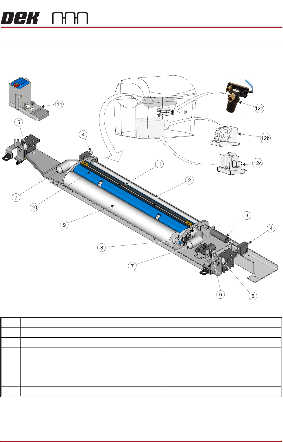
Figure 24-1 Blue Under Screen Cleaner
NOTE
Vacuum Filtration Units VF35i is located at the rear of Type 4 machines and
accessed by removing the rear panel.
Item Description Item Description
1 Squeegee Assembly 8 Paper Usage Sensor
2 Take Up Roll 9 Clean Paper Roll
3 Paper Feed Motor 10 Solvent Spray Bar
4 Permanent Magnet (2 positions) 11 External Solvent Tank
5 Electromagnetic Clamp (2 positions) 12a VF10 Venturi Vacuum Filtration Unit
6 Solvent Pump 12b VF35i Vacuum Filtration Unit
7 Vacuum Connector (2 positions) 12c VF25 Vacuum Filtration Unit