192277 - Micron Technical Reference Volume 3 - 第86页
BLUE UNDER SCREEN CLEANER MODULE ELECTRICAL SCHEMATIC 24.6 Technical Reference Manual C hapter Issue 1 0, Jul 16 Figure 24-4 USC with VF10 V acuum Filtration Unit M36 Machine Control Enclosure PC Motherboard USB NextMove…
BLUE UNDER SCREEN CLEANER MODULE
ELECTRICAL SCHEMATIC
Chapter Issue 10, Jul 16 Technical Reference Manual 24.5
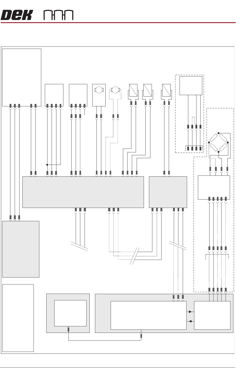
ELECTRICAL SCHEMATIC
Figure 24-3 USC with VF25, V30 or VF35 Vacuum Filtration Unit
M36 Machine
Control Enclosure
PC
Motherboard
USB
NextMove ES
(I/O Node 1)
1
2
4
CAN_H
CAN_L
CAN GND
M36PL35
16SK08
Cleaner
Squeegee Bar
16SOL08
DIG OUT 14
0V
I/Ps
CAN Bus
O/Ps
9SK63
1
4
3
6
7
9PL64
Solvent
Load Cell
9SE26
NextMove
Interface
M36PL09
Solvent ‘Time To Go’ (TTG) Option
1
2
10
12
14
8
7
5
1
AN IN0 -
AN IN0 +
0V USR
+12V
-12V
M37 Power Supply Module
Solvent
Level Amp
-V
+V
-IN
+IN
Vacuum Filtration Unit
NOTE
For Vacuum sensing
Option refer to circuit
185229.
L
N
E
Vac
Pump
Supply
Main Machine
I/O Node 2
N2SK2
CAN In
N2PL4
7
2
3
9
21
L
N
E
M37PL35
M35SK02
M35SK01
1
2
Screen Clean
I/O Node 4
N2SK3
7
2
3
9PL69
1
4
3
6
7
Level +
Ext Service Panel
AGND
0V USR
+12V
-12V
CAN Out
N4SK3
7
2
3
CAN Out
N4SK2
7
2
3
CAN In
1
2
N4PL6
8SK13
R/H Clean
Home Clamp
8SOL20
N4PL2
DIG OUT 0
0V
1
2
3
4
1
2
8SK11
L/H Clean
Home Clamp
8SOL19
1
2
DIG OUT 0
0V
N4PL5
1
2
3
4
DIG OUT 3
0V
+12V
Sig
0V
(L)
N4PL4
4
5
6
Screen Cleaner
Home
8SE10
DIG IN 2
DIG OUT 1
8SK76
8SK71
1
2
N4PL1
4
5
6
DIG IN 1
Paper Low/
Paper Usage
8SE18
Solvent
Pump
8M14
0V
24V
M
M
Paper Feed
Motor
8M5
8SK72
1
2
DIG OUT 2
0V
+12V
Sig
0V
(L)
N/C
NOTE
The breaks in the CAN Bus chain
reflect that additional I/O Nodes
may be fitted, refer to Machine
Control chapter for the complete
CAN Bus chain.
9SE69
Solvent
Float
Sensor
969PL
9PL130
+V
0V
Output
E BY DEK Variation
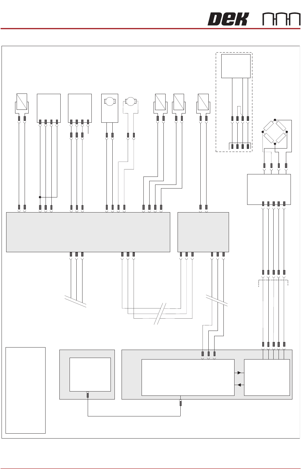
BLUE UNDER SCREEN CLEANER MODULE
ELECTRICAL SCHEMATIC
24.6 Technical Reference Manual Chapter Issue 10, Jul 16
Figure 24-4 USC with VF10 Vacuum Filtration Unit
M36 Machine
Control Enclosure
PC
Motherboard
USB
NextMove ES
(I/O Node 1)
1
2
4
CAN_H
CAN_L
CAN GND
M36PL35
16SK08
Cleaner
Squeegee Bar
16SOL08
DIG OUT 14
0V
I/Ps
CAN Bus
O/Ps
9SK63
1
4
3
6
7
9PL64
Solvent
Load Cell
9SE26
NextMove
Interface
M36PL09
1
2
10
12
14
8
7
5
1
AN IN0 -
AN IN0 +
0V USR
+12V
-12V
Solvent
Level Amp
-V
+V
-IN
+IN
Main Machine
I/O Node 2
N2SK2
CAN In
N2PL4
7
2
3
9
21
Screen Clean
I/O Node 4
N2SK3
7
2
3
9PL69
1
4
3
6
7
Level +
Ext Service Panel
AGND
0V USR
+12V
-12V
CAN Out
N4SK3
7
2
3
CAN Out
N4SK2
7
2
3
CAN In
8SK13
R/H Clean
Home Clamp
8SOL20
N4PL2
DIG OUT 0
0V
1
2
3
4
1
2
8SK11
L/H Clean
Home Clamp
8SOL19
1
2
DIG OUT 0
0V
N4PL5
1
2
3
4
+12V
Sig
0V
(L)
N4PL4
4
5
6
Screen Cleaner
Home
8SE10
DIG IN 2
DIG OUT 1
8SK76
8SK71
1
2
N4PL1
4
5
6
DIG IN 1
Paper Low/
Paper Usage
8SE18
Solvent
Pump
8M14
0V
24V
M
M
Paper Feed
Motor
8M5
8SK72
1
2
DIG OUT 2
0V
+12V
Sig
0V
(L)
N/C
NOTE
The breaks in the CAN Bus chain
reflect that additional I/O Nodes
may be fitted, refer to Machine
Control chapter for the complete
CAN Bus chain.
M35SK01
1
2
1
2
N4PL6
Vacuum Unit
8SOL29
DIG OUT 3
0V
9SE69
Solvent
Float
Sensor
969PL
9PL130
+V
0V
Output
E BY DEK Variation
BLUE UNDER SCREEN CLEANER MODULE
ADJUSTMENTS AND SETTINGS
Chapter Issue 10, Jul 16 Technical Reference Manual 24.7
ADJUSTMENTS AND SETTINGS
CAUTION
SOLDER PASTE AND SOLVENTS. WHEN USING OR HANDLING ANY SOLDER
PASTE OR SOLVENT FORMULATION THE MANUFACTURERS’ SAFETY DATA
SHEETS MUST BE STRICTLY ADHERED TO.
MANDATORY
TOXIC CHEMICALS MAY BE PRESENT. SAFETY GLOVES MUST BE WORN.
MANDATORY
TOXIC CHEMICALS MAY BE PRESENT. EYE PROTECTION MUST BE WORN.
Screen Cleaner
Home
1. Select Maintenance.
2. Select Diagnostics.
3. Use Next or Previous to highlight Screen Cleaner.
4. Select Select Module.
5. Use Next or Previous to highlight Toggle Screen Cleaner Home Clamp.
6. Select Run Diagnost to release the electromagnetic clamps.
7. Move the cleaner by hand towards the rear of the machine until the error
message ‘Screen Cleaner Out Of Position’ is displayed.
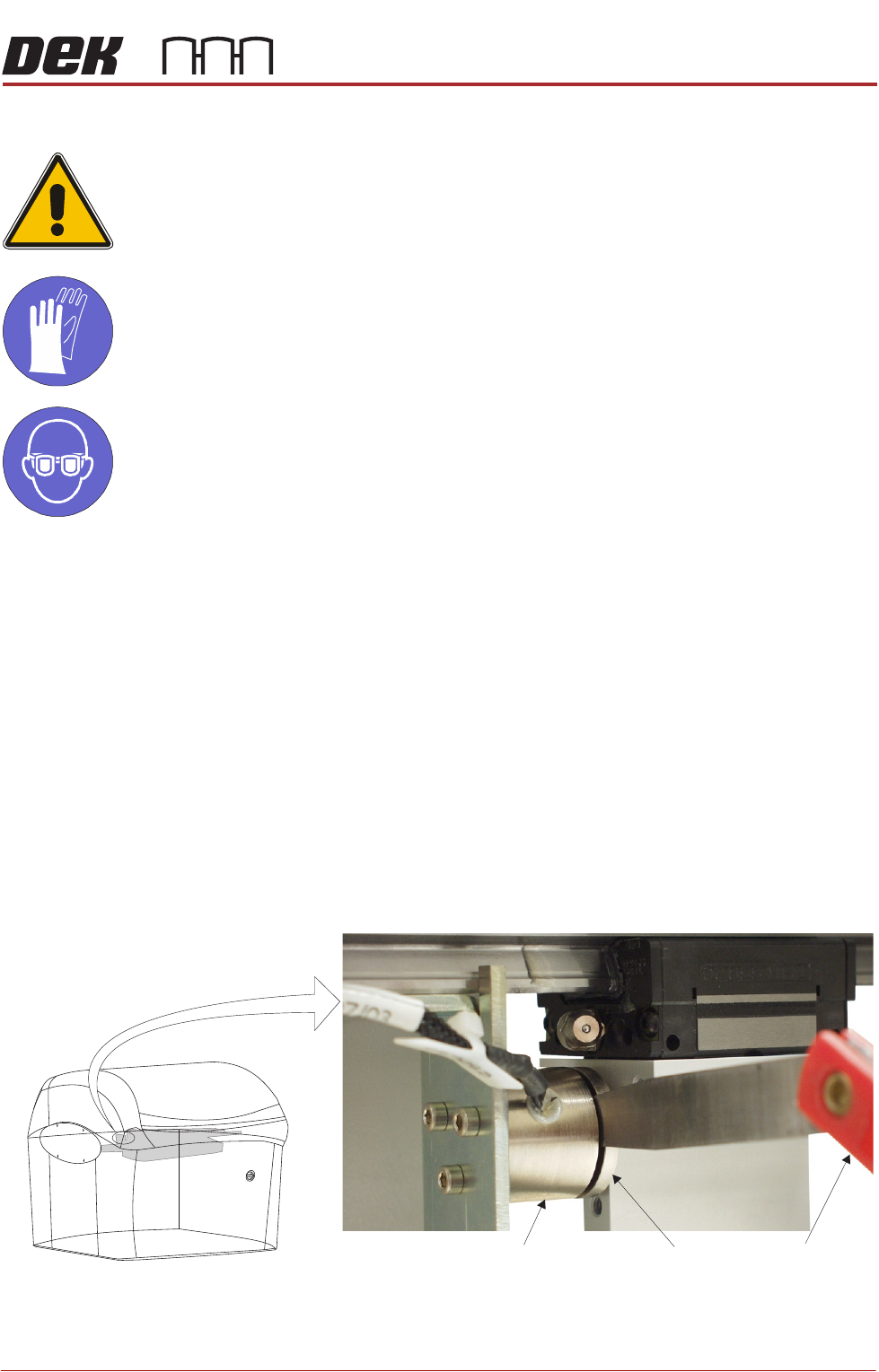
8. Using a 2.0mm feeler gauge positioned between the left hand stencil
cleaner home electromagnetic clamp (8SOL19) and the clamp plate, pull the
cleaner towards the front of the machine. With the clamp plate held lightly
against the feeler gauge, ensure that the error message remains displayed.
9. Repeat Step 8 using a 1.5mm feeler gauge, ensure the error message has
extinguished.
View on Front of Machine
Feeler GaugesElectromagnetic Clamp
Clamp Plate