SM431说明书.pdf - 第291页
X-Y Frame 6-19 8. 按下图中的序号顺 序分离滚珠丝杠。分离过程 中请注意滚珠丝杠与 Y1 Plate 发 生碰撞受损略倾斜进行分离。 Y1 Plate 1 2 3 4
Samsung Component Placer SM431 Service Manual
6-18
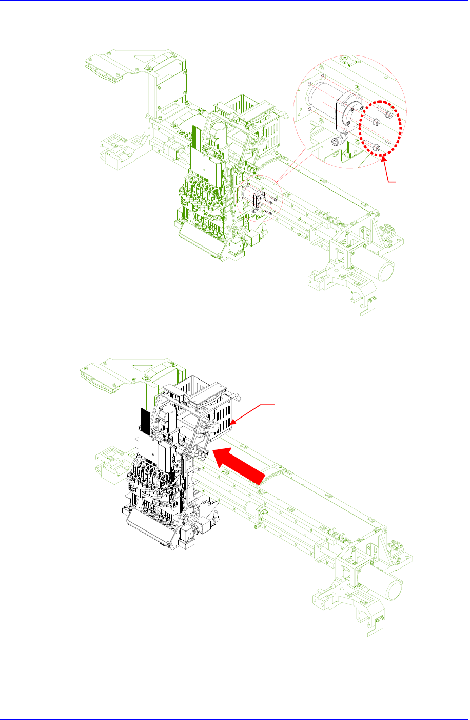
6. 拧开把Ball Screw固定在Head Module的固定螺丝(4-M5*20)后,从Head Module
中拆卸Ball Screw Nut
7. 把Head Module最大限度的以下图箭头方向进行移动。
Head Module
Ballscrew Nut
(4-M5*20)
X-Y Frame
6-19
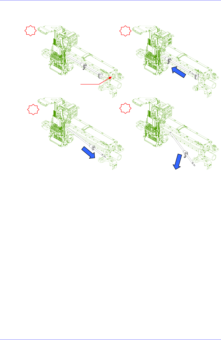
8. 按下图中的序号顺序分离滚珠丝杠。分离过程中请注意滚珠丝杠与Y1 Plate发
生碰撞受损略倾斜进行分离。
Y1 Plate
1
2
3
4
Samsung Component Placer SM431 Service Manual
6-20
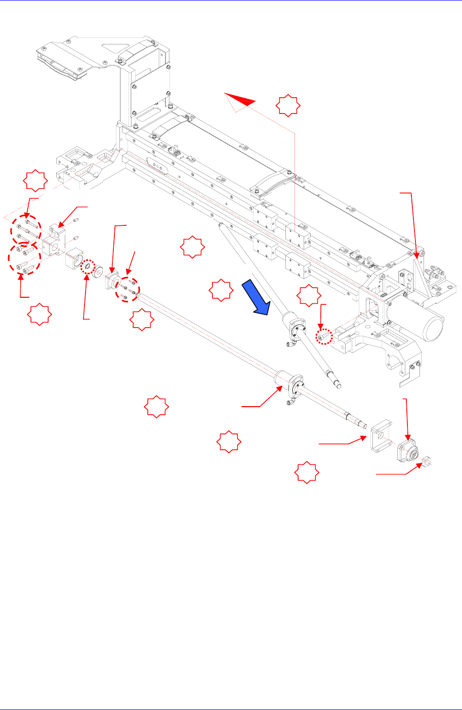
下面是拆卸Ballscrew时的参考图
9. 更换Ball Screw
10. 以拆卸的逆序组装Ball Screw.
4-M4*30
4-M3*8
Ball Screw Nu
t
(4-M5*20)
Cushion X Front
(4-M4*25)
Lock Nut
Ball Screw 分离
Y1 Plate
1
8
3
5
Head Module 移动
9
10
4-M6*20
C-Ring
2
4
7
6
BRG Support-X
Cushion X Rubber
M4
Support Unit