00193732-02.pdf - 第52页
2 Retrofit Instructions for PCB Camera Multicolor, HS-50 / HS-60 SIPLACE HS- 50/HS-60 2.6 Changeover at Main Distribution Frame 11/2004 Edition 52 2 2 : Detach and ide ntify all the term inals at co nnector X6dp on termi…
SIPLACE HS-50/HS-60 2 Retrofit Instructions for PCB Camera Multicolor, HS-50 / HS-60
11/2004 Edition 2.6 Changeover at Main Distribution Frame
51
2.6.1 Disconnect the Wiring, Remove the PCBs
: For info, see also the circuit diagram Fig. 2.14.6 (= status before conversion).
: Before detaching the wiring, identify the wires in the main distributor as shown in the above
circuit diagram (flags 1 - 5).
: To do this, use insulating tape and water-resistant felt-tip pen.
: Use a slotted-head screwdriver, size 1, for the catch clamp connections X6dp and X1dq:
Detach the plug-in connectors of the identified wires (1 - 5) on the "Distributor illumination flash"
board.
: At X6dp GND, only detach the fixing for the zero wire that runs from X6dp GND to the 0 V bus-
bar (see Fig. 2.14.6).
: The zero wire detached at X6dp will be needed again (see cable W5 in Fig. 2.14.8).
: At X1dq Zero, only detach the fixing for the zero wire that runs to the 0 V busbar (see Fig.
2.14.6).
This zero wire will not be needed again, but is left in the cable duct.
2
2
2
2
2
2
2
2
2
2
2
2
2
2
2
2
2 Retrofit Instructions for PCB Camera Multicolor, HS-50 / HS-60 SIPLACE HS-50/HS-60
2.6 Changeover at Main Distribution Frame 11/2004 Edition
52
2
2
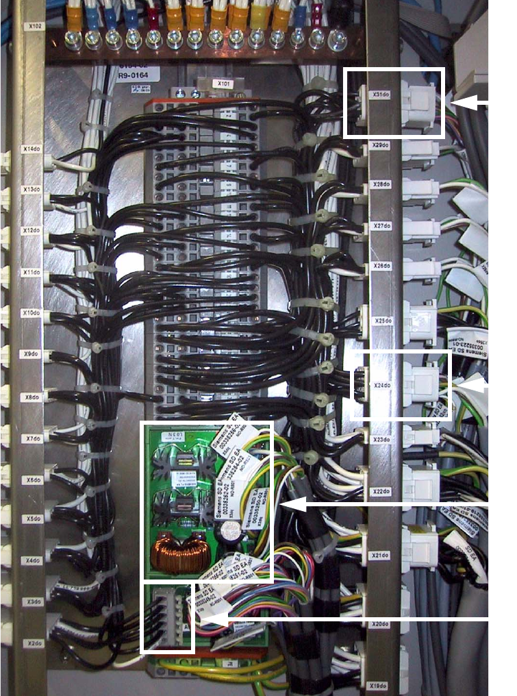
: Detach and identify all the terminals at connector X6dp on terminal block X101 / distributor il-
lumination and flash.
: Detach the two wires at X1dq (Zero and +34V). Wrap them with insulating tape since these
wires are no longer needed.
2
X6dp
Power supply
SM motors
X31do
X24do
SIPLACE HS-50/HS-60 2 Retrofit Instructions for PCB Camera Multicolor, HS-50 / HS-60
11/2004 Edition 2.6 Changeover at Main Distribution Frame
53
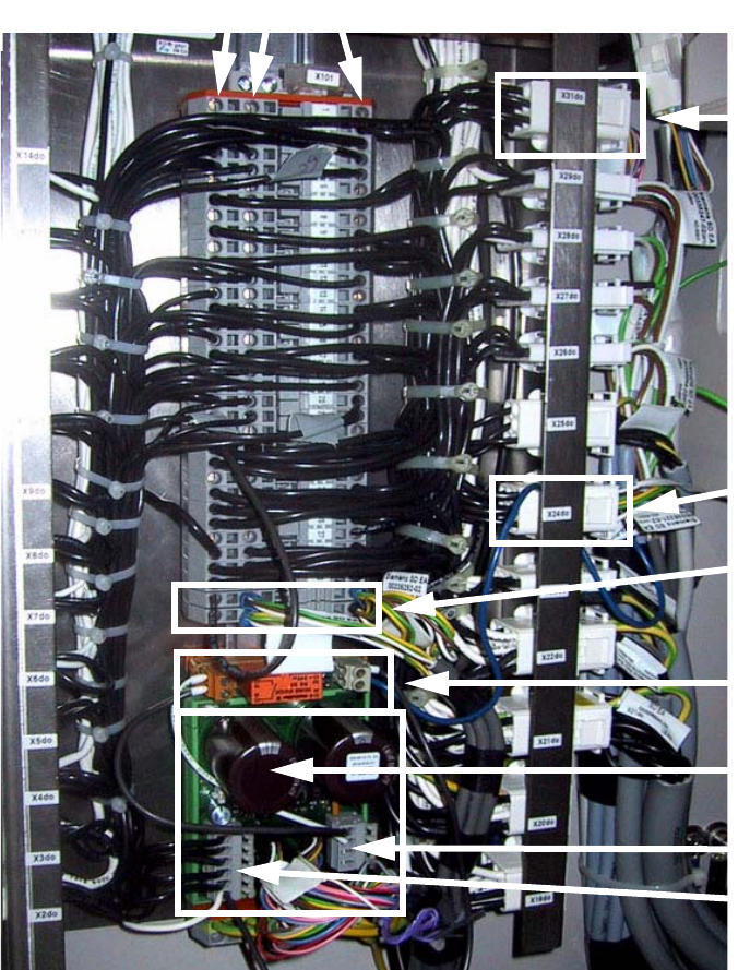
: Detach all the remaining plug-in connectors for the camera illumination and power supply to
the SM motors.
: Remove the two boards from the top-hat rail.
: Detach the MATE-N-LOK plug-in connectors X24do / 9 and X31do / 6.
2.6.2 Fit the boards and relays, etc., and connect up the wiring
: For info, see also the circuit diagram Fig. 2.14.8 (= status after conversion).
2
Terminal 41 and 42
Power supply
to stepping motor
Relay K1
Illumination
converter
X7
X6
X24do
X31do
Catch clamp connector
B
A
C